background image

Important Information

NOTE:

This product is designed for installation with the electrical and water supplies located through the

wall.

Grounding Instructions

This product should be grounded. In the event of an electrical short circuit, grounding reduces the
risk of electric shock by providing an escape wire for the electric current. This product is equipped
with a cord having a grounding wire with a grounding plug. The plug must be plugged into an
outlet that is properly installed and grounded.

WARNING: Risk of electric shock.

Improper use of the grounding plug can result in a risk of

electric shock.

If repair or replacement of the cord or plug is necessary, do not connect the grounding wire to either
flat blade terminal. The wire with insulation having an outer surface that is green with or without
yellow stripes is the grounding wire.

Check with a qualified electrician or service personnel if the grounding instructions are not
completely understood, or if in doubt as to whether the product is properly grounded.

This product is factory equipped with a specific electric cord and plug to permit connection to a
proper electric circuit. Make sure that the product is connected to an outlet having the same
configuration as the plug. No adapter should be used with this product. Do not modify the plug
provided — if it will not fit the outlet, have the proper outlet installed by a qualified electrician. If
the product must be reconnected for use on a different type of electric circuit, the connection should
be made by qualified service personnel.

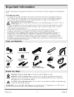
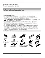
Tools and Materials

Before You Begin

WARNING: Risk of electric shock.

Disconnect the power before servicing.

WARNING: Risk of electrical shock.

Connect only to a properly-grounded, grounding-type

receptacle which is protected by a Ground-Fault Circuit-Interrupter (GFCI). Do not remove the
grounding pin or use a grounding adapter.

CAUTION: Risk of hazardous gases.

If a new toilet is not installed immediately, temporarily place

a rag in the floor flange opening.

IMPORTANT!

The water supply input pipe must be a minimum of 1/2

copper pipe or 3/4

PEX tube to

provide the minimum water flow for this product to operate properly.

Masking 
Tape

Pencil or Felt 
Tip Marker

Assorted Screwdrivers

Supply Stop

5/16" x 2-1/4" T-Bolts

Drill and 1/4" bit

Caulk Gun

Caulk

Rags

Silicone Grease 
or Soap

Socket Wrench 
with 1/2" Deep Socket

1221754-2-C

2

Kohler Co.

Summary of Contents for K-4026

Page 1: ...uide Toilet with Bidet Seat M product numbers are for Mexico i e K 12345M Los números de productos seguidos de M corresponden a México Ej K 12345M Français page Français 1 Español página Español 1 K 4026 1221754 2 C ...

Page 2: ...g to permit connection to a proper electric circuit Make sure that the product is connected to an outlet having the same configuration as the plug No adapter should be used with this product Do not modify the plug provided if it will not fit the outlet have the proper outlet installed by a qualified electrician If the product must be reconnected for use on a different type of electric circuit the ...

Page 3: ...16 500 mm If the installation is in Canada install this unit in accordance with the Canadian Electrical Code Part 1 Observe all local plumbing and building codes Carefully inspect the new toilet for any damage There is a wiring schematic on the inside of the access cover Consult the Homeowners Guide for user directions Consult the Homeowners Guide for troubleshooting instructions Kohler Co 3 12217...

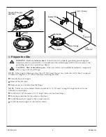
Page 4: ...when it is opened Confirm the rough in is 12 305 mm before installing the toilet Turn off the water supply Remove the old toilet Remove the wax residue from the flange NOTE T bolts are not included T bolts should be 2 1 4 57 mm in length Longer bolts will cause difficulty in installation Install two 5 16 diameter x 2 1 4 long T bolts into the floor flange Mark the centerlines for the outlet on the...

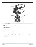
Page 5: ...Align the tank over the floor flange and T bolts Lower the tank onto the floor flange with the slots in the base of the tank aligned with the T bolts Carefully align the tank on the centerline CAUTION Risk of product damage Only apply downward pressure to the tank cylinder Do not press on the tank components other than the cylinder or damage may occur Press down evenly on the rim of the cylinder t...

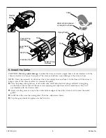
Page 6: ...e nuts Wrench tighten the nuts one quarter turn past hand tight with a socket wrench Connect the water supply hose to the open port on the elbow Connect the water supply hose to the water supply stop Confirm the cap on the elbow is tight Open the water supply stop T Bolt Washer Nut Base of Tank Assembly Connect to the supply stop Flexible Hose Capped Port Water Supply Hose 1221754 2 C 6 Kohler Co ...

Page 7: ...er level in the tank To adjust the water level use a flat blade screwdriver to carefully turn the adjustment rod on the inlet valve Turning the rod counterclockwise will lower and clockwise will raise the water level If further adjustment is required remove several inches of water from the tank and allow it to refill Confirm the water level is correct Repeat until the correct water level is reache...

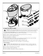
Page 8: ...h wire refill tube electrical plug and bidet wiring plug on the floor at the location of the rear access opening and tape them on the centerline so they will not interfere with the vitreous shell Apply silicone grease or soap to the inside bottom edges of the collar where it will contact the outlet gasket Install the collar onto the outlet gasket Push the collar down firmly Clip the spray shield i...

Page 9: ...the trapway in the vitreous shell seats fully in the outlet gasket If the vitreous shell does not sit evenly on the floor the trapway may not be properly seated Adjust the vitreous shell as needed until the trapway is properly seated Reconnect the water supply hose to the water supply if it was disconnected Connect the Wires CAUTION Risk of personal injury Make sure the plug if plug in connection ...

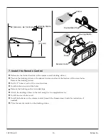
Page 10: ...s Install anchors in each of the holes Remove the backing on the two sided tape Attach the docking station to the wall using the two supplied screws Install the screw hole covers Install the batteries in the remote control consult the Homeowners Guide for instructions if needed Place the remote control on the docking station 38 965 mm 66 1676 mm 36 914 mm Docking Station Remote Control Screw Doubl...

Page 11: ...ion properly 9 Secure the Vitreous Shell CAUTION Risk of product damage Do not overtighten the screws when tightening The vitreous shell may chip or break if the screws are overtightened Insert a screw through each grommet Insert a screw in each of the holes on the side of the vitreous shell and tighten securely Do not overtighten Install a cap over each screw The caps should be flush with the ext...

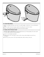
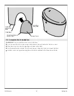
Page 12: ...e the access cover over the opening in the back of the toilet Caulk around the base of toilet Do not caulk the area where the access cover meets the floor Confirm correct seat operation using the seat functions outlined in the Homeowners Guide Toilet Back Access Cover Caulk the base of the toilet Do not caulk base of access cover Cut with a utility knife 1221754 2 C 12 Kohler Co ...

Page 13: ...rt avec ou sans rayures jaunes est le câble de mise à la terre Vérifier auprès d un électricien qualifié ou dépanneur en cas de doute par rapport aux instructions de mise à la terre ou à la bonne mise à la terre du produit Ce produit est équipé en usine avec un cordon et une fiche électriques spécifiques pour permettre le branchement à un circuit électrique adéquat S assurer que le produit est con...

Page 14: ... débit d eau minimum pour que ce produit puisse fonctionner correctement AVIS Le Code canadien de l électricité exige que les prises installées dans les salles de bain soient placées à 39 3 8 1000 m au moins d une baignoire ou d une douche si cela est pratique mais en aucun cas à moins de 19 11 16 500 mm Si l installation se trouve au Canada installer cette unité conformément au Code canadien de l...

Page 15: ...er que le raccordement se trouve à 12 305 mm avant d installer la toilette Couper l arrivée d eau Retirer l ancienne toilette Retirer le résidu de cire de la bride REMARQUE Les boulons en T ne sont pas inclus La longueur des boulons en T doit être de 2 1 4 57 mm L installation sera difficile si les boulons sont plus longs Installer deux boulons en T d un diamètre de 5 16 x 2 1 4 de longueur dans l...

Page 16: ...sol et les boulons en T Abaisser le réservoir sur la bride de sol avec les fentes dans la base du réservoir aligné sur les boulons en T Aligner avec précaution le réservoir sur la ligne centrale ATTENTION Risque d endommagement du produit Appliquer seulement une pression vers le bas sur le cylindre du réservoir Ne pas appuyer sur les composants de réservoir autres que le cylindre vu que ceci pourr...

Page 17: ... écrous à la clé d un quart de tour au delà du serrage à la main avec une clé à douilles Raccorder le tuyau d arrivée d eau au port ouvert sur le coude Raccorder le tuyau d arrivée d eau au robinet d arrêt d eau Vérifier que le capuchon du coude est bien serré Ouvrir complètement l arrêt d arrivée d eau Boulon en T Rondelle Écrou Base de l ensemble de réservoir Connecter au robinet d arrêt d arriv...

Page 18: ...voir Pour ajuster le niveau d eau utiliser un tournevis à lame plate pour tourner avec précaution la tige de réglage sur la valve d entrée Le niveau de l eau s abaisse lorsque la tige est tournée dans le sens antihoraire et s élève lorsqu elle est tournée dans le sens horaire Si un réglage supplémentaire est nécessaire enlever plusieurs pouces d eau du réservoir et laisser ce dernier se remplir Co...

Page 19: ...ge du bidet sur le sol à l emplacement de l ouverture de l accès arrière et les fixer avec du ruban adhésif sur la ligne centrale afin de les empêcher d interférer avec la coque vitrée Appliquer de la graisse à la silicone ou du savon sur les bords inférieurs intérieurs du collier à l emplacement où il entre en contact avec le joint de bouchon femelle Installer le collier sur le joint de bouchon f...

Page 20: ...oude S assurer que le siphon de la coque vitrée est bien assis dans le joint de bouchon femelle Si la coque vitrée n est pas assise de manière uniforme sur le sol le siphon pourrait ne pas être bien en place Ajuster la coque vitrée selon les besoins jusqu à ce que le siphon soit bien en place Reconnecter le tuyau d arrivée d eau s il a été déconnecté Connecter les fils ATTENTION Risque de blessure...

Page 21: ...Installer la coque vitrée cont Connecter le faisceau de câblage du bidet et le faisceau de câblage de la pompe Kohler Co Français 9 1221754 2 C ...

Page 22: ...rage dans chaque trou Retirer la pellicule dorsale du ruban à deux côtés Attacher la station d accueil sur le mur avec les deux vis fournies Installer les chapeaux de trous de vis Installer les batteries dans la télécommande consulter le guide du propriétaire pour obtenir des instructions si nécessaire Placer la télécommande sur la station d accueil 38 965 mm 66 1676 mm 36 914 mm Station d accueil...

Page 23: ...correctement 9 Sécuriser la coque vitrée ATTENTION Risque d endommagement du produit Ne pas trop serrer les vis pendant le serrage La coque vitrée peut s écailler ou se briser si les vis sont trop serrées Insérer une vis à travers chaque passe fil Insérer une vis dans chaque trou situé sur le côté de la coque vitrée et bien fixer en place Ne pas trop serrer Installer un chapeau sur chaque vis Les ...

Page 24: ... la toilette Poser du mastic autour de la base de la toilette Ne pas appliquer de mastic à l emplacement où le couvercle d accès entre en contact avec le sol Vérifier le bon fonctionnement du siège en utilisant les fonctions de siège décrites dans le guide du propriétaire Arrière de la toilette Couvercle d accès Mettre du mastic sur la base de la toilette Ne pas mettre de mastic sur la base du cou...

Page 25: ...s amarillas es el alambre de conexión a tierra Si tiene alguna duda de si el producto está bien conectado a tierra o si las instrucciones de conexión a tierra no están completamente claras solicite la verificación de un electricista calificado o de un profesional de servicio Este producto viene equipado de fábrica con un cable y un enchufe eléctrico que permiten conectarlo a un circuito eléctrico ...

Page 26: ... tubería PEX de 3 4 como mínimo para permitir la mínima tasa de flujo de agua para que este producto funcione correctamente AVISO El Código Eléctrico Canadiense requiere que los tomacorrientes instalados en baños estén ubicados de ser práctico a por lo menos 39 3 8 1000 mm de la bañera o de la ducha pero en ningún caso a menos de 19 11 16 500 mm Si la instalación se hace en Canadá instale esta uni...

Page 27: ...tancia de instalación sea de 12 305 mm antes de instalar el inodoro Cierre el suministro de agua Retire el inodoro viejo Quite los residuos de cera de la brida NOTA Los pernos en T no se incluyen Los pernos en T deben medir 2 1 4 57 mm de longitud Sería difícil hacer la instalación con pernos más largos Instale dos pernos en T de 5 16 de diámetro x 2 1 4 de longitud en la brida en el suelo Marque ...

Page 28: ...da del piso y los pernos en T Baje el tanque sobre la brida del piso con las ranuras en la base del tanque alineadas a los pernos en T Alinee con cuidado el tanque en la línea central PRECAUCIÓN Riesgo de daños al producto Solo aplique presión hacia abajo al cilindro del tanque No oprima en los componentes del tanque que no sean el cilindro ya que podrían ocurrir daños Oprima hacia abajo de manera...

Page 29: ...e vuelta adicional después de haberlas apretado a mano Conecte la manguera de suministro de agua al puerto abierto en el codo Conecte la manguera de suministro de agua a la llave de paso de suministro de agua Confirme que la tapa en el codo esté bien firme Abra la llave de paso de suministro de agua Perno en T Arandela Tuerca Base del ensamblaje del tanque Conecte a la llave de paso de suministro ...

Page 30: ... en el tanque Para ajusta el nivel de agua con un destornillador de punta plana haga girar con cuidado la varilla de ajuste en la válvula de entrada Al hacer girar la varilla hacia la izquierda baja el nivel de agua y sube al hacerla girar hacia la derecha Si se requieren más ajustes saque varios centímetros de agua del tanque y deje que se vuelva a llenar Confirme que el nivel de agua sea el corr...

Page 31: ...l enchufe de cableado del bidet en el piso en el lugar de la abertura de acceso posterior y péguelos en la línea central de tal forma que no interfieran con la carcasa vitrificada Aplique grasa de silicona o jabón a los bordes inferiores interiores del collarín donde hará contacto con el empaque de la salida de drenaje Instale el collarín en el empaque de salida de drenaje Empuje el collarín hacia...

Page 32: ...n en la carcasa vitrificada quede asentada por completo en el empaque de la salida Si la carcasa vitrificada no queda asentada de manera uniforme en el piso es posible que la boca de sifón no esté bien asentada Haga ajustes a la carcasa vitrificada lo necesario hasta que la boca de sifón quede bien asentada Vuelva a conectar la manguera de suministro de agua al suministro de agua si la había desco...

Page 33: ...Instale la carcasa vitrificada cont Conecte el interruptor de nivel y el tubo de llenado Conecte el arnés de cableado del bidet y el arnés de cableado de la bomba Kohler Co Español 9 1221754 2 C ...

Page 34: ...ificios Retire el protector de adhesivo en la cinta adhesiva de doble cara Fije la estación de conexión a la pared con los dos tornillos provistos Instale las cubiertas de los orificios para los tornillos Instale las pilas en el control remoto de ser necesario consulte las instrucciones en la Guía del propietario Coloque el control remoto en la estación de conexión 38 965 mm 66 1676 mm 36 914 mm E...

Page 35: ... vitrificada PRECAUCIÓN Riesgo de daños al producto No apriete demasiado los tornillos al apretarlos La carcasa vitrificada podría despostillarse o romperse si los tornillos se aprietan demasiado Introduzca un tornillo a través de cada ojal Introduzca un tornillo en cada uno de los orificios en el lado de la carcasa vitrificada y apriete bien No apriete demasiado Instale una tapa sobre cada uno de...

Page 36: ...erior del inodoro Aplique sellador alrededor de la base del inodoro No aplique sellador en el área donde la cubierta de acceso hace contacto con el piso Confirme el funcionamiento correcto del asiento con las funciones del asiento que se indican en la Guía del propietario Parte posterior del inodoro Cubierta de acceso Aplique sellador a la base del inodoro No aplique sellador a la base de la cubie...

Page 37: ...1221754 2 C ...

Page 38: ...1221754 2 C ...

Page 39: ...1221754 2 C ...

Page 40: ...USA Canada 1 800 4KOHLER México 001 800 456 4537 kohler com 2015 Kohler Co 1221754 2 C ...

Reviews: