8. Install the Power Data Supply
DANGER: Risk of electrocution.
Disconnect the electricity to the working area at the main breaker
panel before performing the installation steps for hardwiring.
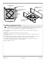
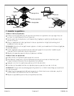
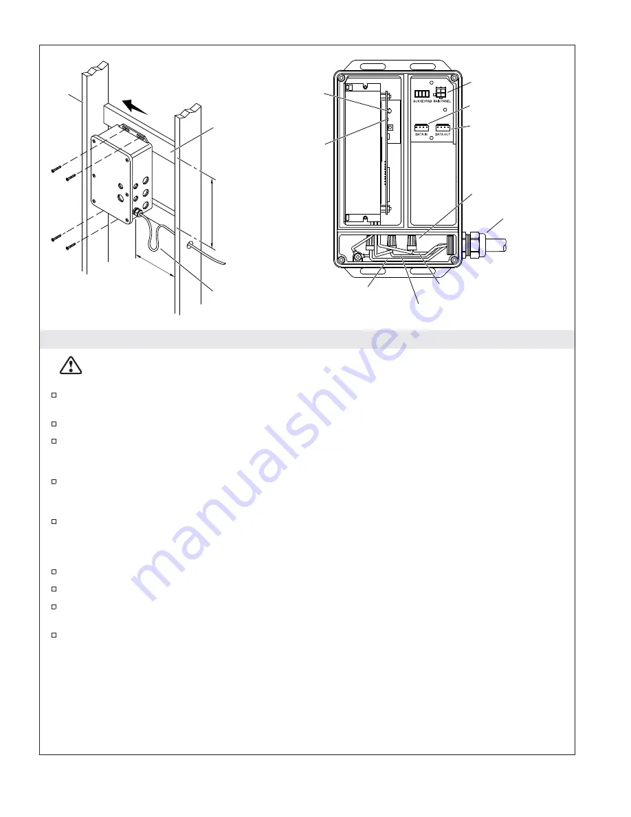
The PDS is designed to fit within a service closet or 2x6 stud cavity with access panel. The PDS
must be within 25’ (7.62 m) of the lighted rain panel.
Install adequate bracing for mounting the PDS.
Route electrical wire to the service closet or 2x6 stud framing, within 24
″
(610 mm) of the PDS.
Make sure the wire is in a position to reach the PDS where electrical connections can be made, and
allow enough wire to create a drip loop.
Position the PDS box within the closet or stud cavity to allow room for cover removal and
connecting the cables. If possible, connect the cables through the side holes rather than the cover
holes to ease cover removal for servicing.
Attach the PDS to structural framing or another secure surface using standard wood or drywall
screws (not supplied). Mounting boards may need to be installed between stud framing.
Make Hardwire Connections
Remove the PDS cover.
Feed electrical wire through the 1/2
″
NPT hole into the power connection chamber of the PDS.
Using wire nuts, connect the Line (black or brown), Neutral (white or blue with white), and Ground
(green or green with yellow stripe) wires.
Following the electrical codes for internal wire bending, carefully tuck the wires into the PDS
housing. Ensure the wires will not be pinched when reinstalling the PDS cover.
6" (152 mm)
Min
Mounting
Board
Position to allow room
for cable connection.
2x6
Drip
Loop
8-1/4"
(210 mm)
LED
Ground: Green or
Green with Yellow Stripe
Neutral: White or Blue with White
Line: Black or Brown
Fuse
1/2" NPT
DTV+ Data Cable
To Rain Panel
100-240 VAC
Wire Nut
Not Used
Kohler Co.
11
1235394-2-A


