- 29 -
- 29 -
44
43
42
12
Characteristics of the system
Starter motor:
lh rotation direction (pinion side), 12V voltage
rating, power 1.1 kW.
Internal alternator:
12V - 280W
Voltage regulator:
electronic, with controlled diodes and
indicator connection for battery recharger
Recommended battery:
In standard start conditions: 12V - 50Ah/255 A DIN
In heavy-duty start conditions: 12V - 60Ah/300 A DIN
Optional accessories:
control strip with remote control switch
and OIL ALARM plant.
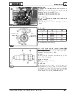
Illustration in fig. 42:
1.
Ignition key -
2.
Voltage regulator -
3.
Starter motor -
4.
Battery -
5.
Alternator -
6.
Pressure switch -
7.
Low battery
charge indicator -
8.
Low oil pressure indicator.
CABLES: Colour x Section mm
2
CABLE COLOURS: B= white
M= brown
N= black
R= red
V= green
Checking the system
1.
make sure that the connections between the regulator and
alternator are correct and in good conditions
2.
detach the wire from the remote control switch from the
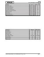
terminal and fit on a d.c. amperometer (
A
,fig. 43)
3.
connect a d.c. voltmeter to the battery terminals (
V
, fig. 43)
4.
make a few no-load starts or introduce a
80-100W
lamp load
at the battery lugs to keep the battery voltage below
13V
.
5.
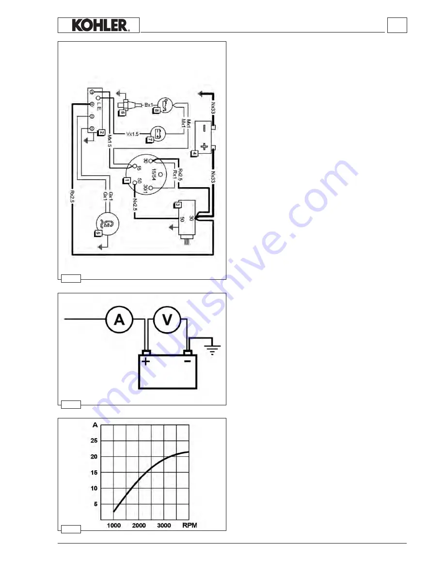
accelerate the engine to a
3000 rpm
rate. The current
indicated on the amperometer must correspond to the values
in fig. 44.
6.
disconnect the load (if any) and keep the engine at the
above mentioned rate for a few minutes. The battery voltage
must progressively increase until reaching about
14.2 V
.
Meanwhile, the charge voltage must drop to a minimum value
of about
2A
, with a speed determined by the battery charge
condition.
7.
if charge current is missing or is less than the given values,
check the alternator and replace the voltage regulator if
necessary.
ELECTRICAL EQUIPMENT
Workshop Manual KD500 _ cod. ED0053029390 -
1° ed
_rev.
00


