TP-6903 5/16a
Installation and Removal Procedures 85
5.1. Air-Fuel Mixer, Adapter, and
Throttle Body Assembly
WARNING
Explosive fuel can cause fires and severe burns.
If a gaseous odor is detected, ventilate the area and
contact an authorized service technician.
LPG (Liquefied Petroleum Gas) is extremely
flammable and tends to settle in low areas where a
spark or flame could ignite the gas.
Do not start or
operate this engine in a poorly ventilated area where
leaking gas could accumulate and endanger the safety of
persons in the area.
NG (Natural Gas) is extremely flammable, is lighter
than air, and rises.
Do not start or operate this engine in
a poorly ventilated area where leaking gas could
accumulate and endanger the safety of persons in the
area.
To ensure personal safety, installation and repair of
LPG/NG fuel supply systems must be performed only by
qualified LPG/NG system technicians. Improperly installed
and maintained LPG/NG equipment could cause the fuel
supply system or other components to malfunction,
causing gas leaks.
Observe federal, state, and local laws governing LPG/NG
fuel, storage, and systems.
Refer to the Engine Service Manual for detailed
assembly and disassembly instructions.
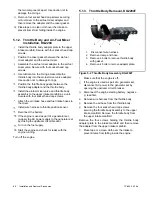
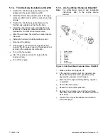
5.1.1. Throttle Body and Air-Fuel Mixer
Removal, KG2204
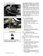
Figure 5-1 Component Exploded View, KG2204
Note:
To loosen the four mounting bolts securing the
air-fuel mixer valve and throttle body assembly to the
upper intake manifold, cut off a hex wrench as needed
to fit into the tight location.
Make sure that the engine is off.
If the engine is used as part of a generator set,
disconnect AC power to the generator set by
opening the upstream circuit breaker.
Disconnect the engine starting battery, negative
(-) lead first.
Shut off the fuel supply.
Relieve the fuel system pressure.
Remove wire harness from the throttle body.
Remove the air intake hose and fuel intake hose
from the air-fuel mixer. Ventilate the area to clear
fumes.
Remove the four socket head cap screws
securing the air-fuel mixer valve and throttle body
assembly to the upper intake manifold. Remove
air-fuel mixer valve and throttle body as a unit
from the upper intake manifold.
Remove the four screws holding the throttle body
adapter plate to the intake manifold and then
remove the adapter from the upper intake
manifold.
To separate the air-fuel mixer valve from the
throttle body, use a rotational motion while pulling
1.
Throttle body adapter plate
2.
Throttle body gasket
3.
Throttle body
4.
Air-fuel mixer adapter
5.
Mixer gasket
6.
Air-fuel mixer
1
2
3
4
5
6
Summary of Contents for KG2204
Page 8: ...8 Safety Precautions and Instructions TP 6903 5 16a Notes ...
Page 44: ...44 Diagnostic Troubleshooting Codes TP 6903 5 16a Notes ...
Page 58: ...58 Fuel System Troubleshooting TP 6903 5 16a Notes ...
Page 100: ...100 TP 6903 Notes ...
Page 105: ...Notes ...
Page 106: ...Notes ...
Page 107: ......


