TP-6903 5/16a
Installation and Removal Procedures 87
5.1.4. Throttle Body Installation, KG2204
Position the throttle body gasket between the
adapter and the upper intake manifold.
Install the throttle body adapter plate to the upper
intake manifold. Secure with four socket head cap
screws.
Position the throttle body gasket between the
throttle body adapter and the throttle body.
Install the air-fuel mixer valve and throttle body
assembly to the upper intake manifold as a unit.
Secure with four socket head cap screws.
Attach the air intake hose and fuel intake hoses to
the mixer.
Install wire harness to throttle position sensor.
Reconnect the battery.
If the engine is used as part of a generator set,
re-apply the AC power supply to the generator set
by closing the upstream circuit breaker.
Turn on the fuel supply.
Start the engine and check for leaks with the
engine running.
Turn off the engine.
5.1.5. Air-Fuel Mixer Removal, KG2204T
Note:
For turbocharger removal and installation
instructions, refer to the engine service
manual.
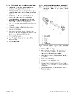
Figure 5-3 Air-Fuel Mixer Exploded View, KG2204T
Make sure that the engine is off.
If the engine is used as part of a generator set,
disconnect AC power to the generator set by
opening the upstream circuit breaker.
Disconnect the engine starting battery, negative
(-) lead first.
Shut off the fuel supply.
Relieve the fuel system pressure.
Remove the air intake hose and the fuel intake
hose from the air-fuel mixer. Ventilate the area to
clear fumes.
Loosen the clamp at the adapter connection to
the turbocharger.
1.
Air-fuel mixer
2.
Mixer gasket
3.
Adapter
4.
O-ring
5.
Clamp
6.
Washer
7.
Screw
8.
Turbocharger
2
3
4
5
6
3
1
2
4
5
8
6
7
Summary of Contents for KG2204
Page 8: ...8 Safety Precautions and Instructions TP 6903 5 16a Notes ...
Page 44: ...44 Diagnostic Troubleshooting Codes TP 6903 5 16a Notes ...
Page 58: ...58 Fuel System Troubleshooting TP 6903 5 16a Notes ...
Page 100: ...100 TP 6903 Notes ...
Page 105: ...Notes ...
Page 106: ...Notes ...
Page 107: ......

