background image

12

1493936-W2-A

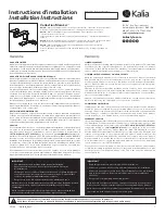
Warning! Turn off the electrical and water supplies before proceeding with 

the installation of the shower.

Cover

Caution!

 Do not drill into 

buried cables or pipes.

Screws

Screw

Service 

Tunnel

Remove  the  three  screws  that 

hold the cover on and remove 

the cover.

Remove the service tunnel.

Using the installation template 

supplied, mark the positions 

of the 

three 

fixing holes.  

Note:

 Ensure that there are 

sufficient lengths of supply pipe 

and electrical cable to reach the 

connection points.

Remove the installation template 

and drill three holes to suit the 

fixing screws and wall plugs. 

Caution!

 Do not drill into cables 

or pipes in the wall.

1

3

4

2

Installation

Summary of Contents for Mira 1.1746.007

Page 1: ...493936 W2 A These instructions must be left with the user Mira Sport Max with Airboost 9 0 and 10 8 kW Installation and User Guide For SPARES ADVICE or REPAIRS please call us free on 0800 001 4040 UK only ...

Page 2: ...uction concerning use of the appliance in a safe way and understand the hazards involved 2 Children shall not be allowed to play with the shower 3 DO NOT restrict the water flow from the shower outlet temporarily bending the shower hose or blocking the shower head while in use can cause a hot shot of water to be discharged 4 Cleaning and user maintenance shall not be made by children without super...

Page 3: ...et mode point handset away from body and make sure that the water temperature has stabilised before continuing to shower 16 Use caution when altering the water temperature always check the temperature before continuing to shower 17 Switch the shower off at the electrical isolating switch when not in use This is recommended with all electrical appliances 18 Installation of the shower must be carrie...

Page 4: ...fore entering the shower 26 The water supplies to this product must be isolated if the product is not to be used for a long period of time If the product or pipework is at risk of freezing during this period they should also be drained of water 27 If the shower is dismantled during installation or servicing then upon completion an inspection must be made to ensure all electrical connections are ti...
Page 5: ... x Case Inserts 1 x Installation Template 1 x Installation User Guide 1 x Guarantee Brochure 1 x Mira Sport Max with Airboost Electric Shower INLET CONNECTOR CN1 PL4 CN3 L N PL5 E BROWN A BLUE B GREEN D GREEN D GREEN C GREEN H RED K RED J BLUE G BLUE F BROWNE BROWN N BROWN L BROWN M ORANGE P GREY S GREY T BLACK R SOLENOID TERMINAL BLOCK AIR PUMP HEATER TANK ELECTRONICASSEMBLY RELAY PCBA ELECTRONIC...

Page 6: ...Max with Airboost electric showers have separate controls for power selection and temperature flow adjustment in addition an Airboost function further enhances the showering experience A unique flow regulator stabilises any temperature changes caused by water pressure fluctuations which can result from taps being turned on or off or toilets being flushed Product Variant Model No Colour Sport Max w...

Page 7: ...ature 30 C Minimum Ambient Temperature 2 C Dimensions Height 358 mm Width 215 mm Depth 90 mm Plumbing Sport Max with Airboost Variant 9 0 10 8 Minimum Dynamic Pressure 70 kPa 0 7 bar 100 kPa 1 0 bar Maximum Dynamic Pressure 500 kPa 5 bar Minimum Static Pressure 20 kPa 0 2 bar Maximum Static Pressure 1000 kPa 10 bar Maximum Inlet Temperature 30 C Minimum Inlet Temperature 2 C Inlet Connection 1 2 B...

Page 8: ...pliances and are subject to conditional connection If the main electrical supply fuse is rated less than 80 Amps the local electricity supply company must be contacted to confirm if the electrical supply is adequate The Mira Sport Max with Airboost range of showers complies with the requirements of the UK s water regulations Disposal and Recycling End of Product Life Electrical and electronic devi...

Page 9: ...erproof flat and even wall surface 8 DO NOT fit the shower to the wall and tile up to the case 9 DO NOT seal the gap between the shower and the wall surface 10 The showerhead should be positioned so that it discharges down the centre line of the bath or across the opening of a shower cubicle 11 The showerhead must be directed away from the shower unit during normal use the showerhead must not spra...

Page 10: ...l installation until the plumbing has been completed and checked for leaks Hose retaining ring fitted and shower fittings fixed at a suitable height preventing dirty water backflow Note There will be occasions when the hose retaining ring will not provide a suitable solution for Fluid Category 3 installations in these instances an outlet double check valve must be fitted this will increase the req...

Page 11: ...the consumer unit to the shower 5 DO NOT supply any other electrical equipment including extractor fans or pumps via this product 6 This shower must be provided with means for local disconnection that is incorporated into the fixed wiring in accordance with the relevant local wiring regulations This must be a double pole switch which has at least 3 mm contact separation in each pole The switch can...

Page 12: ...hold the cover on and remove the cover Remove the service tunnel Using the installation template supplied mark the positions of the three fixing holes Note Ensure that there are sufficient lengths of supply pipe and electrical cable to reach the connection points Remove the installation template and drill three holes to suit the fixing screws and wall plugs Caution Do not drill into cables or pipe...

Page 13: ...the incoming water supply falling entering the shower from the top or rising entering the shower from the bottom NOTE DO NOT use an incoming supply entering the shower directly from the back Add an elbow to the supply pipe and connect it as a rising or falling supply Upper and lower case inserts are supplied and should be fitted NOTE Trim the inserts if necessary to fit incoming electrical or wate...

Page 14: ...n ensure connections and back case are not under any stress due to misaligned pipework or electrical cables Terminal Block Outlet Connector Cold Water Supply Pipe Inlet Connector Strip back sufficient outer cable insulation to enable routing to terminal block Fit an earth sleeve to the earth wire Tighten the screws in the terminal block ensure the wires are secure and tight Electrical Cable N Neut...

Page 15: ...stall the shower fittings Ensure the earth bonding complies with relevant regulations Replace the service tunnel Plug the multi connector into the cover PCB socket Note The multi connector will only locate correctly into the socket in one direction Ensure the temperature control dial is aligned with the spindle then replace the cover Tighten the three cover screws Do not use alternative screws to ...

Page 16: ...iffuser into the showerhead then carefully tighten the shower hose onto the showerhead Note Make sure the hose washer is fitted and that the diffuser is pushed fully home into the showerhead Fit the showerhead into the clamp bracket Identify the different ends of the air pipe tube Air pipe adapter is inserted into the shower outlet Air pipe diffuser is inserted into the showerhead Hose Washer Diff...

Page 17: ...the Low Eco or High button is pushed the Airboost Pump will activate for approximately 4 seconds Water flows freely within a few seconds temperature remains cool Slowly turn the temperature control to the hot position 4 6 5 TEMPERATURE LOW COLD 0 15 secs HOT Push ECO button Eco button illuminates Flow is reduced and temperature remains cool 9 8 7 ECO HIGH Turn temperature control back to the midwa...

Page 18: ...se further Temperature will rise slightly Adjust temperature as required Flow rate will adjust automatically Push START STOP button Light in the button goes out Switch off the electrical supply The shower will purge water from its tank for a few seconds TEMPERATURE 10 11 12 13 14 15 16 17 HIGH Check Airboost function Aerated water will flow from the Showerhead MAX AIRBOOST 5 10 secs COLD HOT 5 10 ...

Page 19: ...tments to stabilise and reach the showerhead Check water temperature before entering shower 4 6 5 0 15 COLD HOT H Push START STOP button Light in the button goes out and shower continues to run for a few seconds 8 9 7 Push Airboost button if required The Airboost button will illuminate and briefly flash Aerated water flows from the Showerhead MAX AIRBOOST Normal Flow Airboost Enabled Airboost Enab...

Page 20: ... outlets are opened whilst showering providing the minimum pressure does not fall below 70 kPa 0 7 bar 9 kW 100 kPa 1 0 bar 10 8 kW Selected Showering Temperature Example of how shower temperature stabilises due to pressure changes TEMPERATURE POWER MAX The Effect of Seasonal Changes Incoming mains water temperature is not constant throughout the seasons of the year i e cooler during the winter wa...

Page 21: ...cover Connect or re connect Multi Connector into cover PCB Replace cover PCB Shower cycles from hot to cold ON ECO HIGH Showerhead blocked Hose kinked or blocked Water pressure below minimum required for shower operation Temperature control or power control setting too high Remove and descale showerhead Check hose and replace if necessary Make sure incoming mains water stopcock and or shower isola...

Page 22: ...r Contact local water company Replace flow valve Low or no flow ON ANY Water supply pipework or inlet filter restricted by a blockage or partial blockage Insufficient water supply pressure flow for operation Flow valve faulty Heater tank excessively scaled Showerhead blocked Hose kinked or blocked Other outlets e g toilet garden hose washing machine etc drawing water while the shower is being used...

Page 23: ...F ANY Flow valve solenoid or Start Stop switch faulty Replace as necessary Shower fails to produce hot water when set on Eco High setting ON ECO HIGH Insufficient water supply Possible failure of the relay PCB or thermal switch Contact local water company Use a suitable device to check the continuity of the relay PCB or thermal switch and replace parts as necessary Water leaks from the bottom of t...

Page 24: ...f a malfunction of the shower a fault finding table is provided in this guide detailing possible causes and remedies that may be carried out by non qualified personnel WARNING TO REDUCE THE RISK OF FIRE ELECTRIC SHOCK INJURY OR PRODUCT DAMAGE User Maintenance Always read the IMPORTANT SAFETY INFORMATION for your shower Cleaning De scaling the Showerhead and inspecting the hose and diffuser It is I...

Page 25: ...ecessary 5 Reassemble parts in reverse order Warning Failure to keep the showerhead nozzles clear or inspect the hose for blockage or internal external collapse can restrict the flow rate from the shower This may cause damage to the shower or result in the temperature delivered to the user rising to unsafe levels with a risk of scalding You MUST ALWAYS check the temperature before using the shower...

Page 26: ...6 7 Remove the shower hose Note Retain the Hose Washer for further use Remove the three cover retaining screws and remove the cover Unplug the multi connector and place the cover to one side Remove the service tunnel Use a suitable spanner to remove the filter from the inlet connector assembly Hold a wrench across the flats of the inlet connector assembly to prevent damage to the connector whilst ...

Page 27: ...522 Flow Valve 10 8 kW model 1746 525 Wire Pack not shown 1746 495 Screw Pack identified A 1746 456 Component Pack identified B 1746 523 Cover PCB 1746 526 Air Pipe 1746 710 9 0kW 1746 711 10 8kW Heater Tank PCB Max 1746 529 Air Pump 1746 435 Inlet Clamp 1746 524 Outlet Connector B B B A 1746 437 Coil A A A 1746 521 1746 522 Flow Valve A 1746 449 Terminal Block ...

Page 28: ...oad Cheltenham Gloucestershire GL52 5EP 14648 Guarantee Your product has the benefit of our manufacturer s guarantee which starts from the date of purchase This guarantee only applies in the United Kingdom and Republic of Ireland Activating Your Guarantee Registering your guarantee is quick and simple To ensure your product is covered please register online Scan the QR code to activate your guaran...

Reviews: