background image

10

Warning! Turn off the electrical and water supplies before proceeding with the
installation of the Mira Escape. The electricity must be turned off at the mains
and the appropriate circuit fuse removed, if applicable.

Note! An installation template is supplied to help you install the Mira Escape.

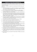
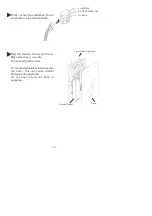
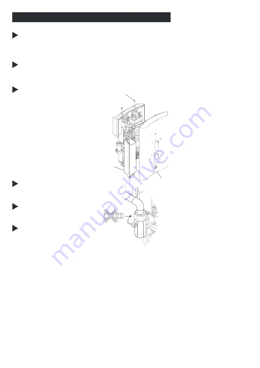
Remove the three cover retaining
screws, the cover and the service
tunnel.

Cover

Cover Retaining
Screw

Service Tunnel

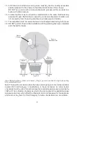
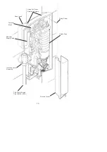
Determine the direction of the inlet
water supply: top (falling), bottom
(rising), or back inlet .

Note! Make sure that the back inlet
does not go directly back into the wall.
Use a soldered elbow.

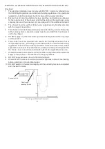
Swivel the inlet connector assembly
to suit. Remove the inlet blanking cap.
Avoid trapping the green earth bonding
wire.

INSTALLATION

Installation of Mira Escape

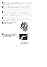
Wall ¿xings are not supplied. For solid wall structures a red rawl plug and a
no. 8 x 1½” countersunk brass or stainless steel screw should be used. For
other wall structures such as panels alternative ¿xings may be required. A
minimum of 3 ¿xing screws should be used.

Summary of Contents for Mira Showers Escape Thermostatic 9.8 kW

Page 1: ...1 Mira Escape Thermostatic 9 0 9 8 kW These instructions must be left with the user Installation and User Guide For SPARES ADVICE or REPAIRS Please call uson 0844 571 5000 UK Only ...

Page 2: ...s caused by water pressure Àuctuations These can result from taps being turned on or off or toilets being Àushed Individual lights indicate ON OFF and LOW FLOW The Mira Escape comes complete with Mira Energise adjustable spray handset with four different spray actions start soothe force and eco Àexible hose clamp bracket assembly slide bar supports hose retaining ring and soap dish On electric sho...

Page 3: ...become frozen is properly insulated 5 DO NOT switch the shower on if there is a possibility that the water in the shower is frozen 6 DO NOT switch the shower on if water starts leaking from the shower case Isolate the electrical supply to the shower immediately 7 DO NOT connect the outlet of the shower to any tap control valve trigger handset or showerhead other than those speci ed for use with th...

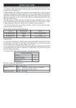
Page 4: ... Case Inserts Tick the appropriate boxes to familiarize yourself with the part names and to con rm that the parts are included Documentation 1 x Installation and User Guide 1 x Installation Template 1 x Guarantee and Registration Document PACK CONTENTS ...

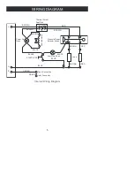
Page 5: ...N BROWN BROWN BROWN BLACK BLACK BLACK RED RED RED WIRING DIAGRAM Thermal Cutout Dual Disc Tank Connection Load Inlet Connector Pressure Power Selector Switch Solenoid Valve Low Flow Neon Power On Neon START STOP L E N Internal Wiring Diagram ...

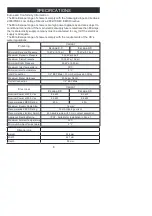
Page 6: ...pe 9 8 Nominal Power at 230 V ac 8 3 kW 9 0 kW Nominal Power at 240 V ac 9 0 kW 9 8 kW Recommended MCB Rating 40 A 45 A Maximum Supply Cable Size 16 mm Recommended RCD Rating 30 mA tripping current Recommended Isolator Switch 45 A double pole with 3 mm contact separation Appliance Sealing Rating IP X4 Suitable for installation in Zone 1 Maximum Ambient Temperature 30 C Minimum Ambient Temperature ...

Page 7: ...tion within the shower area and is tted with a pressure relief valve It must be positioned over a water catchment area with the controls at a convenient height for the user 6 The shower must be tted to a waterproof Àat and even wall surface 7 DO NOT t the shower to the wall and tile up to the case 8 DO NOT seal the gap between the shower and the wall surface 9 The showerhead should be positioned s...

Page 8: ...age for details 17 The installation must not cause the hose to be sharply kinked during normal use 18 DO NOT perform the electrical installation until the plumbing has been completed and checked for leaks Hose Retaining Ring tted and shower ttings xed at a suitable height preventing dirty water backÀow Note There will be occasions when the hose retaining ring will not provide a suitable solution f...

Page 9: ...iring of the mains system A separate supply must be provided from the consumer unit to the shower 5 DO NOT supply any other electrical equipment including extractor fans or pumps via this product 6 This shower must be provided with means for local disconnection that is incorporated into the xed wiring in accordance with the relevant local wiring regulations This must be a double pole switch which ...

Page 10: ...nel Determine the direction of the inlet water supply top falling bottom rising or back inlet Note Make sure that the back inlet does not go directly back into the wall Use a soldered elbow Swivel the inlet connector assembly to suit Remove the inlet blanking cap Avoid trapping the green earth bonding wire INSTALLATION Installation of Mira Escape Wall xings are not supplied For solid wall structur...

Page 11: ... wall and mark through the positions of the xing holes Make sure that the position of these holes do not come in line with any buried cables or pipework Make sure that suf cient electrical supply cable is available for connection to the terminal block Drill and plug the top two xing holes Secure the Mira Escape to the wall with appropriate screws Drill the bottom xing hole with the product in plac...

Page 12: ...REEN YELLOW N BLUE Re t the Service Tunnel and Cover Make sure they t correctly Do not overtighten screws Do not use alternative screws to secure the Cover This can cause internal damage to the appliance Do not seal around the back of appliance Cover Cover Retaining Screw Service Tunnel ...

Page 13: ...13 Cold Water Supply Pipe Bottom Entry Service Tunnel Fixing Screw Holes For Cover Retaining Screws Case Insert Electrical Supply Cable Terminal Block Inlet Connector Assembly Heater Tank ...

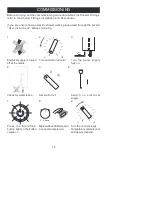
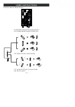
Page 14: ...ceand at a cool temperature Turn the control slowly Temperature remains cool and Àow is reduced Electrical supply is turned off at the mains COLD 0 5 Secs 1 4 3 2 6 5 9 8 7 Before carrying out the commissioning procedure install the Shower Fittings refer to the Shower Fittings Installation and User Guide If you are unsure how an electric shower works please read through the section User Instructio...

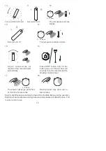
Page 15: ...rom its tank for a few seconds Residual water may drain over a few minutes Set control to III 5 10 Secs 0 5 Secs 13 15 14 16 _ Press STOP button light on the button goes out Shower Àow will continue for a few seconds before stopping Isolate power 17 18 Note A slight hissing sound may be heard from the Mira Escape during operation High mains water pressure and high shower temperatures will affect t...

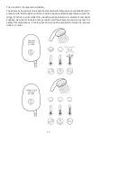
Page 16: ...r the shower the lower the Àow rate and vice versa Heated water is produced by adjusting the Àow of cold water passed through a heater tank The shower has three heater settings How Your Electric Shower Works USER INSTRUCTIONS ...

Page 17: ... across the range from hot to cold whilst also dealing with Àuctuations in electrical and water supplies As a result there is a temperature limit the shower cannot go beyond For safety this temperature is factory set and cannot be adjusted to make the shower hotter or colder Thermostatic Temperature Stable THERMOSTATIC ELECTRIC SHOWER ORDINARY ELECTRIC SHOWER ...

Page 18: ...ecked regularly and replaced if damaged refer to the user maintenance section towards the rear of this guide for details 10 DO NOT store bathroom items on top of the shower case ie Shampoo or shower gel containers 11 Always check the water temperature before entering the shower Sunburn or skin conditions can increase your sensitivity to hot water Make sure that you set the shower to a cooler tempe...

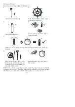
Page 19: ...ned off This may drain over a few minutes Press the Start Stop button light on the button comes on 2 Switch on electrical supply 1 Set to desired position 3 Residual water may drain over a few minutes 7 4 _ Check water temperature before entering shower 5 _ Allow 10 15 seconds for any temperature adjustments to reach the handset 6 Press STOP button light on the button goes out Shower Àow will cont...

Page 20: ...quired operating parameters refer to section Speci cations For a cold shower select I For a summer warm shower select II For a winter warm shower select III During extremes of mains water supply temperature adjust heater setting to obtain a better showering temperature The Effect of Seasonal Changes The Effect of Other Water Devices Example of how shower temperature stabilises due to pressure chan...

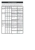
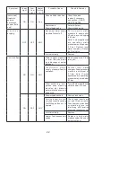
Page 21: ...ration Make sure incoming mains water stopcock and or appliance isolating valve is fully turned on ON OFF II III Temperature dial or Heater setting too high Turn the heater selector knob to setting II or turn the temperature control until a cooler temperature is achieved Thermostatic mechanism is faulty or damaged Replace U n a b l e t o s e l e c t a cool enough shower ON OFF III Due to the rise ...

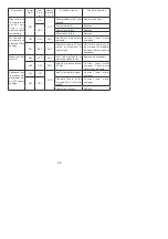
Page 22: ...pework or inlet filter restricted by a blockage or partial blockage Flush supply pipe Clean inlet lter I n s u f f i c i e n t w a t e r supply pressure Àow for operation C ontact local water company Supply pressure must be a minimum of 0 7 bar Note If other appliances are operating pressure may drop below 0 7 bar Other outlets e g toilet garden hose washing machine etc drawing water while the sho...

Page 23: ... water company ON OFF ANY Possible failure of flow valve microswitch or heater tank Check the continuity of the microswitch or heater tank and replace parts as necessary Water will not turn off ON OFF ANY Inlet valve solenoid or start stop switch faulty Replace as necessary ON ON ANY Supply pressure below 0 2 bar C ontact local water company Check mains water static pressure Appliance fails to pro...

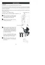
Page 24: ...m of water Unscrew the hose from the showerhead and the shower outlet Inspect the hose Cleaning Many household cleaners contain abrasives and chemical substances and should not be used for cleaning plated or plastic parts or ttings These nishes should be cleaned with a mild washing up detergent or soap solution and then wiped dry using a soft cloth WARNING TO REDUCE THE RISK OF FIRE ELECTRIC SHOCK...

Page 25: ...e Filter as necessary Re t in reverse order making sure the Filter is screwed fully home Do not overtighten Make sure plumbing connections are sealed before restoring electricity supply Refit the cover making sure it is correctly located Do not overtighten the screws Filter SERVICING WARNING There are no user serviceable parts inside the shower Servicing of the shower must only be carried out by q...

Page 26: ... 537 Control Belt 1563 694 Neon Assembly 872 28 Microswitch 3 Pin 1563 547 Satin 1563 548 Chrome 1563 784 White Service Tunnel and Case Inserts B C D A 416 48 Latching Switch 416 51 Coil 1563 538 Cam and Pulley 1563 540 Inlet Valve 1563 522 Cover Seal not shown 1563 541 Screw Pack identi ed A 1563 550 Component Pack Satin identi ed B 1563 551 Component Pack Chrome identi ed C 1563 787 Component Pa...

Page 27: ...Chrome 2 1731 001 Grey Chrome 2 1731 002 Stylish slim line and robust shower seat for use in or outside of the shower area Folds up when not in use Maximum User Weight 150 kg 23 5 stone Note Must be installed onto a solid wall Logic Showerhead Holder White 2 1605 149 White Chrome 2 1605 150 An alternative to the traditional slide bar Often a useful addition when positioned for the smaller members ...

Page 28: ... ompensation for loss of use of the product or conse uential loss of any kind amage or defects caused if the product is repaired or modified by persons not authorised by us or our appointed representative outine maintenance or replacement parts to comply with the re uirements of the TM or TM 3 healthcare schemes Accidental or wilful damage Products purchased ex showroom display What to do if someth...

Reviews: