3: Installation
28
TS_619_00 PW9000DPA S2 User Manual 13/3/17
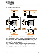
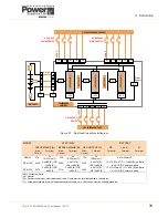
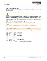
Single feed / dual feed inputs
The UPS input mains and bypass mains terminals can be linked inside the UPS cabinet in what is known as a ‘single feed’
configuration. This configuration, which is used in the majority of installations, only requires one mains supply as illustrated
in the left illustration of Figure 3.2.
When the ‘single feed’ links are removed, the bypass mains terminals must be connected to a mains supply source via a
dedicated bypass mains supply circuit breaker (or fuses). A ‘dual feed’ configured module is shown in the right illustration
of Figure 3.2.
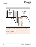
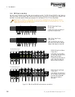
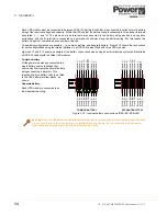
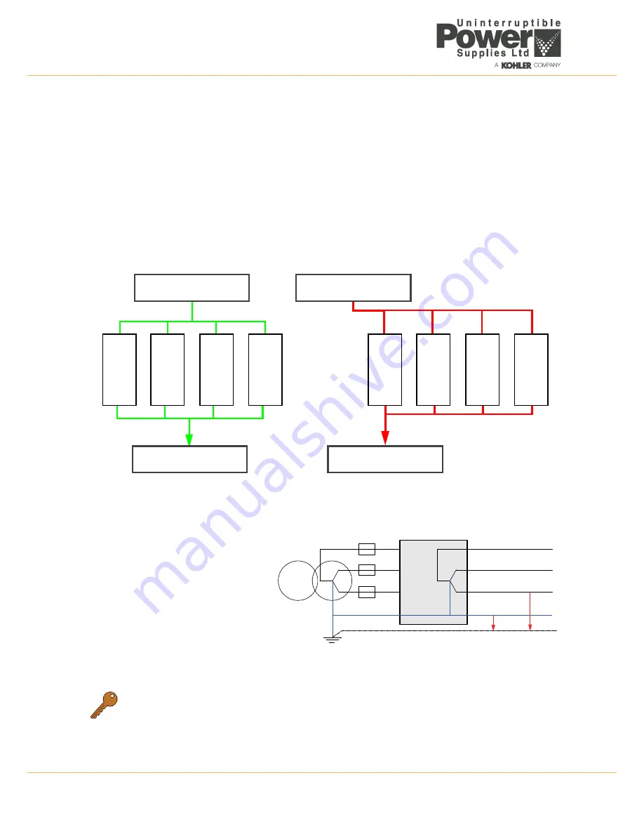
Cabling a parallel cabinet system
In a parallel cabinet installation all the UPS cabinets must be supplied from the same mains power source and the cables
from the mains switchgear panel to each cabinet should be of equal length. Similarly, the UPS output cables connected to
the load switchgear panel should be of equal length (see Figure 3.3) – this helps to balance the load sharing between the
UPS cabinets.
Figure 3.3 UPS Cabinet parallel power cabling considerations
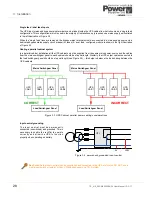
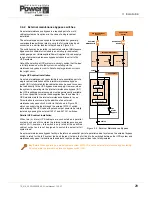
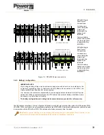
Input neutral grounding
The input neutral must be permanently
connected (unswitched) and grounded. This is
necessary to enable the rectifier to operate
correctly and allow the UPS to function
properly when operating on battery.
Key Point:
As the input neutral must be unswitched and connected to the UPS at all times, DO NOT use a
4-pole input switch or isolator at the LV Distribution panel on a TN-S system.
UPS
CAB 1
UPS
CAB 2
UPS
CAB 3
UPS
CAB 4
UPS
CAB 1
UPS
CAB 2
UPS
CAB 3
UPS
CAB4
CORRECT
INCORRECT
Mains Switchgear Panel
Mains Switchgear Panel
Load Switchgear Panel
Load Switchgear Panel
0V
230V
UPS
Figure 3.4 permanent, grounded input neutral

