:
6
TS_622_02 PowerWAVE 9500DPA User Manual 26/2/19
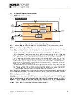
Rectifier (6)
The rectifier (6) converts the UPS input mains to a DC power source that can satisfy the inverter DC power demands over
an input voltage range of between 160V~288V. This wide input voltage range means that the battery is not called upon
even during substantial power dips (brown outs), which maximises battery life and availability. The rectifier control system
uses leading-edge switched-mode techniques which achieves a UPS input power factor of almost unity over its operating
range (0.99 at full rated linear load).
Battery booster/charger (7)
This block has bi-directional functions. When the UPS mains input supply is available, and the rectifier is turned on, the
booster/charger acts as a multi-stage battery charger which uses an intelligent charging profile to optimise the battery life
and ensure the battery recharges quickly following a deep discharge cycle.
If the input mains supply fails, or the rectifier is unable to provide a sufficient output to satisfy the prevailing inverter load,
the battery provides the inverter’s DC operating power source via the booster. The booster contains a DC-DC boost
converter which boosts the battery voltage and provides a regulated DC input to the inverter as the battery discharges to
allow the inverter to operate correctly.
Inverter (8)
The inverter converts the DC voltage produced by the rectifier (or the battery via the boost converter) into a sinusoidal AC
output voltage suitable to connect to the load. In addition to providing output voltage regulation, the inverter control logic
also provides various levels of overload protection, frequency regulation and synchronisation, and output voltage error
detection.
Static switch (9)
The static switch provides a means of connecting the UPS module output to the static bypass line – which is in turn
connected to the UPS bypass mains supply. Working in conjunction with the output contactor, the static switch control
logic is used to transfer the UPS output from the inverter to the static bypass line without a break in the load supply in the
event of an overload or UPS (inverter) malfunction.
Note: A no-break transfer will take place if the inverter frequency and the bypass supply frequency is synchronised.
Inverter output contactor (10)
The inverter output contactor is driven by the UPS module’s control logic and operates in conjunction with the static switch
as part of the bypass/inverter load transfer process. The contactor is also used to isolate the inverter from the UPS output
following certain overload or fault conditions.
Bypass contactor (11)
The bypass contactor is used to isolate the bypass mains from static bypass line if the bypass supply is outside a
specified, or if there is a sustained overload or bypass fault while the UPS is operating on bypass.
2.3.2 UPS Module operational states
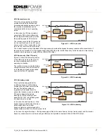
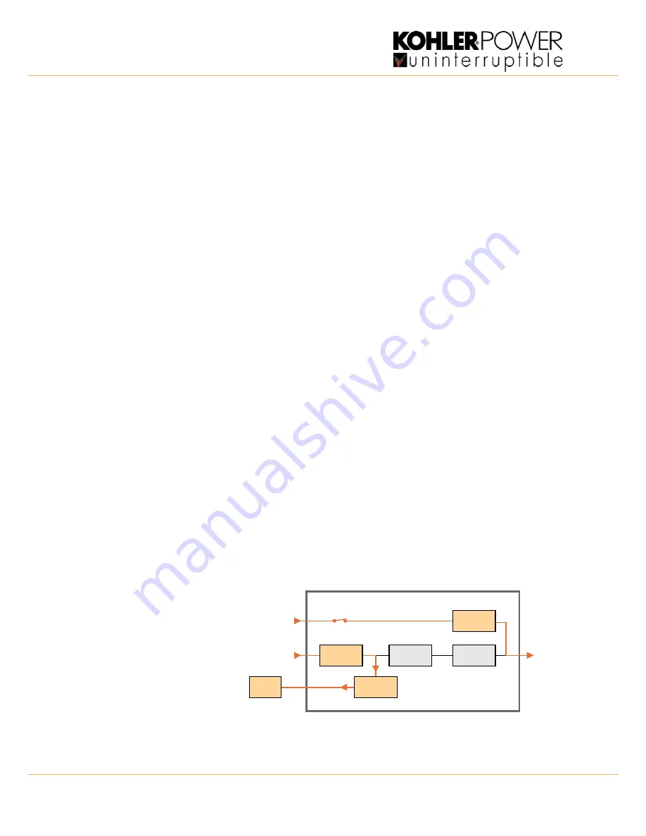
The following simplified block diagrams are used to illustrate the standard operating modes of the UPS module.
Inverter off (load on bypass)
Figure 2.3 shows the internal
operation of the UPS module when
mains power is first applied to the
UPS or the inverter is turned
OFF
from
the module control panel.
If the mains input supply is available,
the battery charger continues to
charge the battery and the static
switch turns on to connect the UPS
output to the bypass supply.
Figure 2.3 Inverter off
RECTIFIER
BATTERY
INVERTER
STATIC
SWITCH
BOOSTER /
CHARGER
INV. Output
Contactor
UPS MODULE
Static bypass line
Bypass
Contactor
UPS Bypass
Mains
UPS Input
Mains
UPS AC
Output


