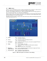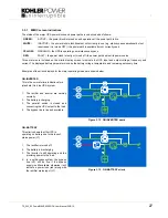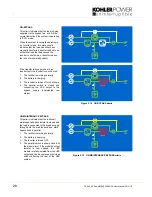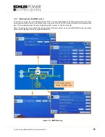
:
30
TS_622_02 PowerWAVE 9500DPA User Manual 26/2/19
3.4
XTRA VFI screen(s)
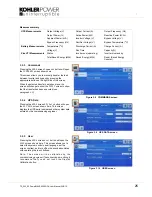
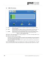
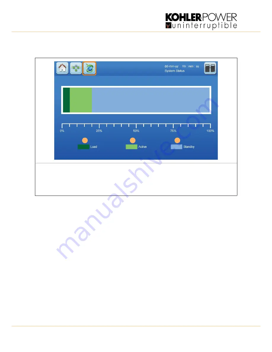
Figure 3.17 Xtra VFI status bar screen
The
XTRA
VFI
STATUS
BAR
screen can be accessed by pressing the
Xtra
VFI
button on the display header bar (only
visible if the Xtra VFI function is enabled).
There are two screens related to the Xtra VFI function:
• The
XTRA
VFI
STATUS
BAR
screen, shown above, provides a bar chart representation of the Xtra VFI operation in
terms of relative capacity, remaining capacity from the active inverters and the additional capacity available from
the inverters currently operating on standby.
• The ‘
XTRA
VFI
MEASURES
’ screen, described in detail on page 24, provides numerical data concerning the module
status and saved energy.
You can cycle between these two screens by pressing the Xtra VFI button on the display header bar. To exit these
screens you must press a different button on the display header bar or select another function in the
MEASURES
screen.
A
Load
The dark green area of the status bar indicates the applied load as a percentage of the UPS
system rated capacity.
B
Active
The light green area of the status bar indicates the remaining capacity of the active inverters – i.e.
those inverters that are turned on, and operating under the control of the Xtra VFI function.
C
Standby
The light blue area of the status bar indicates the capacity of the modules operating on standby
that can be called upon by the Xtra VFI function if required to support any load increase.
A
B
C

