TS_622_02 PowerWAVE 9500DPA User Manual 26/2/19
31
:
3.5
MODULE SELECTION screen
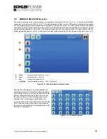
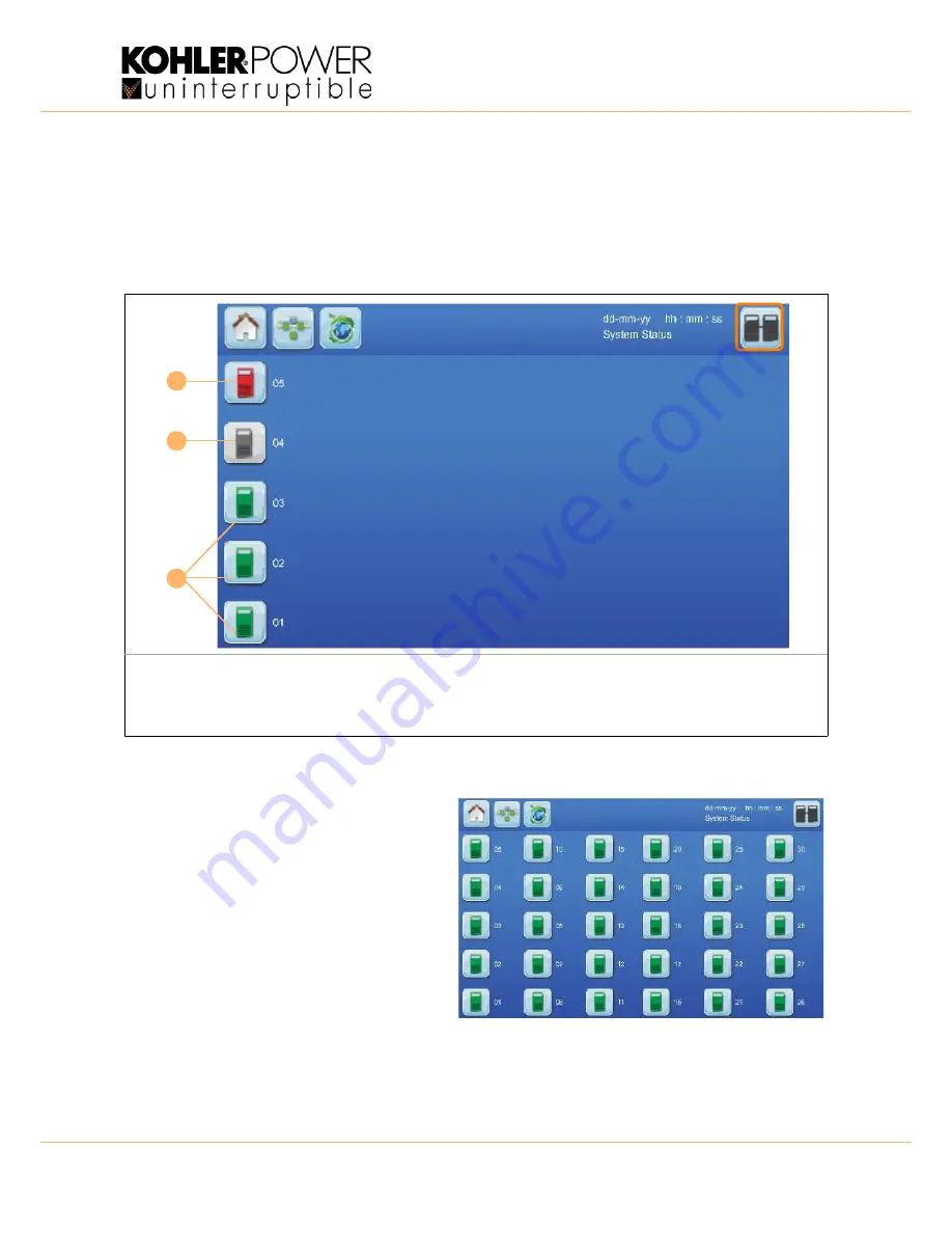
The module selection screen, shown below, is accessed by pressing the
Module
Selection
button on the display
header bar. On opening, the
MODULE
SELECTION
screen displays an icon for each UPS module connected to the system
and immediately indicates its operational status by means of its displayed colour. The UPS modules, which are identified
numerically by the ID number entered into the module’s configuration set-up during commissioning, are shown in vertical
columns representing each UPS cabinet. The diagram below identifies five modules fitted to a single cabinet, with the
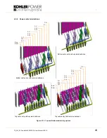
bottom module assigned an ID of 01. A maximum six-cabinet system containing 30 UPS modules is shown in Figure 3.19.
Figure 3.18 Module selection display screen
Note that if a UPS cabinet is not fully populated, the
numbering protocol will not skip the missing module(s).
For example, if there are only four modules fitted in the
first two cabinets there will be no icons shown in the
[05] and [10] slots, but the numbering sequence for
cabinets 2 and 3 will still begin with [06] and [15].
If you press one of the touch-sensitive icon buttons the
MIMIC
screen will open which allows you to observe
the operation and metering for the selected module, as
described in paragraph 3.3.
A
Green
Module in normal operation – on line
B
Grey
Module inactive – turned off
C
Red
Module has a general alarm
Light Blue
Module operating in standby – Xtra VFI mode only
A
B
C
Figure 3.19 30-Module system

