:
40
TS_622_02 PowerWAVE 9500DPA User Manual 26/2/19
4.5.4 Cable sizing
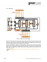
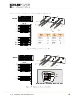
Figure 4.7 ‘Single feed’ input block diagram
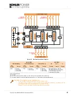
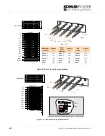
Figures 4.7 and 4.8 identify (in red) the power cables, fuses and other protective devices that must be provided by the
customer for a single-feed and dual-feed connected installation respectively. The table below shows the maximum UPS
input and output current for each set of cables together with the cable termination details. This is provided to assist the
customer in selecting appropriately rated power cables and external switchgear.
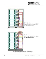
Note: These illustrations show a single set of DC cables (cable D) connected between the UPS and external battery
cabinet. In a ‘common battery’ installation (as shown) the battery positive and negative cables are connected to the battery
busbars which are located adjacent to the UPS input/output mains busbars. In a ‘separate battery’ installation the UPS
battery busbars are removed and the individual battery positive and negative cables are connected directly to the
modules’ battery fuses (F3).
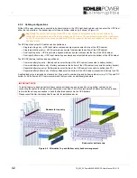
Key Point:
We recommend M12 busbar connections are tightened to 42Nm. and M8 busbar connections
tightened to 24 Nm.
Cable D
Fu
se
D
Ca
bl
e
C
Ca
bl
e
A
IA 1
Maint.
Bypass
3L3
3N
PE
3L1 3L2
PW9500DPA
CABINET
BATTERY 1
UP
S
M
od
ul
e
1
BA
TT
ER
Y
2
1L3
1N
PE
1L1 1L2
PE
PE
F3
UP
S
M
od
ul
e
2
F3
BA
TT
ER
Y
3
UP
S
M
od
ul
e
3
F3
UPS INPUT
MAINS DEVICE
UPS SYSTEM INPUT SUPPLY
UPS SYSTEM OUTPUT
UPS OUTPUT
DEVICE

