background image

 Kohler Co., Kohler WI

113019-

CA

 (1093)

2

IMPORTANT SAFETY INSTRUCTIONS

ATTENTION INSTALLER: INSTRUCTIONS PERTAINING TO RISK OF FIRE, ELECTRIC

SHOCK OR INJURY TO PERSONS

READ AND FOLLOW ALL INSTRUCTIONS

WARNING: When using this unit, always follow basic precautions, including the following:

DANGER: RISK OF ELECTRICAL SHOCK.
The installation must have Class A
Ground-Fault  Circuit-Interrupters (GFCI) for
the whirlpool system.

This will provide additional protection against
line-to-ground shock hazard. 

Such a GFCI should be provided by the installer and
should be tested on a routine basis. 

To test the GFCI, press the test button. The GFCI should
interrupt power. Press the reset button. Power should be
restored.

If the GFCI fails to operate in this manner, there is a
ground current flowing or the GFCI is defective. The
possibility of an electric shock may exist. DO NOT use
this unit. Disconnect the unit and have the problem
corrected by a qualified licensed electrician.

For -J1 and -JA models only: A green colored terminal
(or a wire connector marked “G”, “GR”, “GROUND”, or
“Grounding”) is provided within the terminal
compartment. To reduce the risk of electric shock,
connect this terminal or connector to the grounding
terminal of your electric service or supply panel with a
conductor equivalent in size to the circuit conductors
supplying this equipment.

All models:  A pressure wire connector is provided on
the exterior of the pump or control box within this unit to
permit connection of a No. 8 AWG (8.4 mm

2

)


solid

copper bonding conductor between this unit and all other
electrical equipment and exposed metal in the vicinity, as
needed to comply with local requirements.

DO NOT operate this unit without the guard on the
suction fitting.

Never drop or insert any object into any opening.

Use this unit only for its intended use as denoted in this
manual.  DO NOT use attachments not recommended
by the Kohler Co.

DANGER: To reduce the risk of injury, do not
permit children to use this unit unless they are
closely supervised at all times.

SAVE THESE INSTRUCTIONS

Summary of Contents for Precedence K-1353-AA

Page 1: ...Precedence Baths K 1353 AA K 1354 AA 113019 CA 1093 Copyright 1993 Kohler Co...

Page 2: ...cted by a qualified licensed electrician For J1 and JA models only A green colored terminal or a wire connector marked G GR GROUND or Grounding is provided within the terminal compartment To reduce th...

Page 3: ...ION 10 FIELD WIRE COMPRESSOR 11 Service Requirements 11 Identify Electrical Requirements 11 Connect Control 120 V 60 Hz 11 TEST DOOR SYSTEM 12 Operating Sequence 12 Troubleshoot Door System 12 INSTALL...

Page 4: ...rcuit Interrupter GFCI Air Compressor 120 V 15 A 60 Hz Door seal system rating 120 V 60Hz 3 A C PRODUCT INFORMATION Fixture basin area top area weight Bathing well 43 x 19 1 2 52 x 24 1 2 143 lbs wate...

Page 5: ...ts warranty or otherwise for personal injury or damage caused by any such unauthorized modification Use a separate service for the door air compressor 3 PRODUCT REQUIREMENTS A SUMMARY OF KEY REQUIREME...

Page 6: ...led in new or existing bathrooms For new installations Position plumbing according to roughing indimensions located on page 4 Cap supplies and check for leaks For replacement installations Remove old...

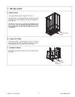
Page 7: ...ose to 60 Size the stud pocket accordingly NOTE The stud pocket must fit the width of the unit exactly The bath is shipped with a spacer bar to pre vent spreading or squeezing of the door opening This...

Page 8: ...upport for the hand spray on vertical slide bar if used Route piping and adapt framing as necessary for the hand spray supply elbow pressure balanced mixer valve and high flow tub filler and valves Re...

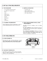
Page 9: ...not level some leveling of the bath area will be necessary Do not support the weight of the bath by the flange Do not use drywall plaster as a means of support Drain Hole Shims B TO ADJUST LEVEL Shim...

Page 10: ...amiliarize yourself with the location of all major components before proceeding to field wiring by a licensed electrician suction elbow adjustment trim kit installation and testing and troubleshooting...

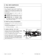
Page 11: ...B IDENTIFY ELECTRICAL REQUIREMENTS The model number is printed on a plate at the seat end of the module The model number identifies electrical rating Electrical connections for each model vary K 1353...

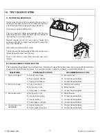
Page 12: ...ter Line 2 Min B TROUBLESHOOT DOOR SYSTEM This troubleshooting guide is for general aid only A Kohler Authorized Service Representative or a qualified electrician should correct all electrical problem...

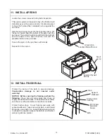
Page 13: ...base with screws Repeat for other apron Supplied Drywall Screw Large Apron Small Apron Supplied Drywall Screws 12 INSTALL FINISH WALL Protect the inside of the bath to prevent damage Construction dam...

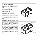
Page 14: ...pressure to secure kick strip to bath base Kick strip 14 CLEAN UP AFTER INSTALLATION Do not use abrasive cleaners as they may scratch and dull the unit surface Use warm water and a liquid detergent to...

Page 15: ...113019 CA 1093 Kohler Co Kohler WI 15...

Page 16: ...113019 CA 1093 Kohler Co Kohler WI...

Reviews: