background image

7

113019-

CA

 (1093)

Kohler Co., Kohler WI

C.  REMOVE APRONS AND INSPECT UNIT

Carefully uncrate and inspect the bath for damage. Do
not remove spacer bar until unit is secured to stud
pocket.

Loosen and remove the screws at the base of the two
aprons. These screws secure the aprons to the pan
base. Save these screws.

Pull bottom of apron away from bath unit and then pull
top down and out from flange in bath rim.

Continue inspection of bath for damage.

Reinstall aprons if unit is not immediately installed.

Return bath to carton during construction to prevent
damage.

Large
Apron

Small
Apron

Supplied Drywall Screws

Spacer
Bar

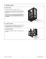
D.  STUD POCKET PREPARATION

Refer to Roughing-In section beginning on page 4.
Measure the exact outside dimension of the bath from
the two front edges of the nailing flange. This should be
close to 60”. Size the stud pocket accordingly.

NOTE: The stud pocket must fit the width of the unit
exactly. The bath is shipped with a spacer bar to pre-
vent spreading or squeezing of the door opening.
This would affect the proper function of the inflat-
able seal.

Construct a recess designed for your particular
installation. Install stud pocket headers.

Construct the required access panel according to
Roughing-In section beginning on page 4.

Design of bath will allow for up to 1/2” of finish floor
material if the bath is installed to the subfloor. For thicker
flooring, raise bath with plywood underlayment to
compensate. This is necessary to allow clearance for
apron removal.

Stud Pocket

NOTE: Refer to instructions

32” Min.

NOTE:  Nailing
flange holes in
unit are 24-3/4”
from base of
unit

Header Nailing
Flange

NOTE: Allow adequate clearance for plumbing.
Centerline of drain is 23-1/8” from back of unit.

E.  PLUMBING PREPARATION

Position plumbing according to roughing-in dimensions.
Cap supplies and check for leaks.

Summary of Contents for Precedence K-1353-AA

Page 1: ...Precedence Baths K 1353 AA K 1354 AA 113019 CA 1093 Copyright 1993 Kohler Co...

Page 2: ...cted by a qualified licensed electrician For J1 and JA models only A green colored terminal or a wire connector marked G GR GROUND or Grounding is provided within the terminal compartment To reduce th...

Page 3: ...ION 10 FIELD WIRE COMPRESSOR 11 Service Requirements 11 Identify Electrical Requirements 11 Connect Control 120 V 60 Hz 11 TEST DOOR SYSTEM 12 Operating Sequence 12 Troubleshoot Door System 12 INSTALL...

Page 4: ...rcuit Interrupter GFCI Air Compressor 120 V 15 A 60 Hz Door seal system rating 120 V 60Hz 3 A C PRODUCT INFORMATION Fixture basin area top area weight Bathing well 43 x 19 1 2 52 x 24 1 2 143 lbs wate...

Page 5: ...ts warranty or otherwise for personal injury or damage caused by any such unauthorized modification Use a separate service for the door air compressor 3 PRODUCT REQUIREMENTS A SUMMARY OF KEY REQUIREME...

Page 6: ...led in new or existing bathrooms For new installations Position plumbing according to roughing indimensions located on page 4 Cap supplies and check for leaks For replacement installations Remove old...

Page 7: ...ose to 60 Size the stud pocket accordingly NOTE The stud pocket must fit the width of the unit exactly The bath is shipped with a spacer bar to pre vent spreading or squeezing of the door opening This...

Page 8: ...upport for the hand spray on vertical slide bar if used Route piping and adapt framing as necessary for the hand spray supply elbow pressure balanced mixer valve and high flow tub filler and valves Re...

Page 9: ...not level some leveling of the bath area will be necessary Do not support the weight of the bath by the flange Do not use drywall plaster as a means of support Drain Hole Shims B TO ADJUST LEVEL Shim...

Page 10: ...amiliarize yourself with the location of all major components before proceeding to field wiring by a licensed electrician suction elbow adjustment trim kit installation and testing and troubleshooting...

Page 11: ...B IDENTIFY ELECTRICAL REQUIREMENTS The model number is printed on a plate at the seat end of the module The model number identifies electrical rating Electrical connections for each model vary K 1353...

Page 12: ...ter Line 2 Min B TROUBLESHOOT DOOR SYSTEM This troubleshooting guide is for general aid only A Kohler Authorized Service Representative or a qualified electrician should correct all electrical problem...

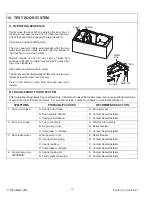
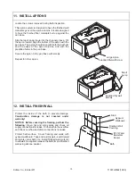
Page 13: ...base with screws Repeat for other apron Supplied Drywall Screw Large Apron Small Apron Supplied Drywall Screws 12 INSTALL FINISH WALL Protect the inside of the bath to prevent damage Construction dam...

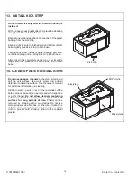
Page 14: ...pressure to secure kick strip to bath base Kick strip 14 CLEAN UP AFTER INSTALLATION Do not use abrasive cleaners as they may scratch and dull the unit surface Use warm water and a liquid detergent to...

Page 15: ...113019 CA 1093 Kohler Co Kohler WI 15...

Page 16: ...113019 CA 1093 Kohler Co Kohler WI...

Reviews: