background image

PRO 12.3 EFI
Generator Service Manual

34 690 01  

8

/16a

KohlerPower.com

1

2

Safety

3

Specifications

6

Troubleshooting

9

Electrical System

17

Disassembly/Inspection and Service

22

Reassembly

IMPORTANT:  Read all safety precautions and instructions carefully before operating equipment. 

Ensure equipment is stopped and level before performing any maintenance or service.
For all engine related maintenance, disassembly and reassembly, refer to service manual of engine 

powering this equipment.

Summary of Contents for PRO 12.3 EFI

Page 1: ...isassembly Inspection and Service 22 Reassembly IMPORTANT Read all safety precautions and instructions carefully before operating equipment Ensure equipment is stopped and level before performing any maintenance or service For all engine related maintenance disassembly and reassembly refer to service manual of engine powering this equipment ...

Page 2: ...eep hands feet hair and clothing away from all moving parts to prevent injury Never operate generator with covers shrouds or guards removed WARNING Accidental Starts can cause severe injury or death Disconnect and ground spark plug lead s before servicing Before working on generator or equipment disable engine as follows 1 Disconnect spark plug lead s 2 Disconnect negative battery cable from batte...

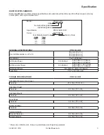
Page 3: ... 22 4 in 770 mm 30 3 in Dry Weight 162 kg 306 lbs AC Rated Power 10 500 Watt 120 Volts x 87 5 Amps 240 Volts x 43 8 Amps AC Maximum Power 12 300 Watt 120 Volts x 102 5 Amps 240 Volts x 51 3 Amps DC Rated Power 100 Watt 12 Volts x 8 3 Amps Fuel Tank 33 0 L 8 7 U S gal TORQUE SPECIFICATIONS1 PRO 12 3 EFI Alternator Frame to Front Cover Fastener 21 0 N m 186 in lb Alternator Shield Fastener 9 0 N m 7...

Page 4: ...9 9 N m 87 in lb Front Cover Fastener 21 0 N m 186 in lb Fuel Tank Fastener 9 0 N m 79 in lb Muffler Shield to Exhaust Studs Retaining Nut 27 8 N m 246 in lb Muffler Shield Fastener 9 0 N m 79 in lb Rotor Through Bolt 21 0 N m 186 in lb Side Rail Fastener 9 0 N m 79 in lb 1 Values are in Metric units Values in parentheses are English equivalents ...

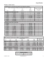
Page 5: ...nglish Fastener Torque Recommendations for Standard Applications Bolts Screws Nuts and Fasteners Assembled Into Cast Iron or Steel Grade 2 or 5 Fasteners Into Aluminum Size Grade 2 Grade 5 Grade 8 Tightening Torque N m in lb 20 8 32 2 3 20 2 8 25 2 3 20 10 24 3 6 32 4 5 40 3 6 32 10 32 3 6 32 4 5 40 1 4 20 7 9 70 13 0 115 18 7 165 7 9 70 1 4 28 9 6 85 15 8 140 22 6 200 5 16 18 17 0 150 28 3 250 39...

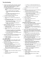
Page 6: ...itation failure Engine not operating at rated RPM Adjust engine running at normal operating temperature to 3600 100 RPM Faulty capacitor Check and replace Faulty windings Check windings resistance High no load voltage Engine not operating at rated RPM Adjust engine running at normal operating temperature to 3600 100 RPM High capacity of capacitor Check and replace Low no load voltage Engine not op...

Page 7: ...tance between exciter leads Compare to value in table Also check resistance from each exciter lead to ground If out of specification or shows resistance to ground then replace stator If within specification proceed to next step 3 Measure μF microfarad value of capacitor with appropriate meter If meter will not measure μF value of capacitor you can use an analog or digital ohmmeter and verify if ca...

Page 8: ...next step 3 Check a Resistance values of all stator windings and rotor windings b Resistance from stator leads to ground c Diodes are good 1 Cut wire on 1 side of each diode from rotor 2 Use a meter set to diode test and check each diode d Resistance from rotor leads to rotor shaft 4 Replace a Any component that does not meet specifications in Alternator Specifications table b If diodes are found ...

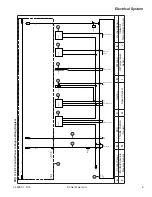
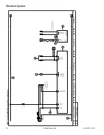
Page 9: ...x 350218 1 AMP 15 15 J2 J2 17 17 J1 J1 14 14 J1 J1 7 7 J2 J2 17 17 10 10 J2 J2 16 16 11 11 12 12 J2 J2 4 4 J2 J2 13 13 J2 J2 14 14 J2 J2 8 8 P ECU 0319E01 0320 05 0318 20 0320 16 0320 07 30 0318 09 1 2 0319F05 10A 080 30 0318 13 080 0319E07 0319E10 0319R12 8 1 E 9 1 3 0 6 1 E 9 1 3 0 4 1 B 9 1 3 0 4 0317 09 0319B20 0320 01 B A E I F D G H J C A Control Panel B ECU C Ignition D Kill Lead E Oxygen S...

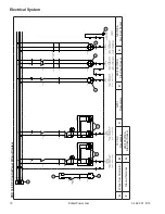
Page 10: ...Y GOLD GROUND TERMINAL G GREEN NEUTRAL TERMINAL W SILVER PHASE1 TERMINAL X GOLD PHASE2 TERMINAL Y GOLD GROUND TERMINAL G GREEN G G G G G G G 0315 19 0315 19 0315 18 0315 18 S2 R2 V J N 0321X01 0315 13 30 30A 1 2 0321Q01 10A 0315 14 31A V J BN BR BS 0321X03 N 2 4 1 2 3 4 5 20R GFCI 1P N T 120V 20A W X VJ 1 1 2 0321Q04 20A R2 R21 W X 0321X07 N 2 4 1 2 3 4 5 20R GFCI 1P N T 120V 20A W X V J2 1 2 0321...

Page 11: ... 34 690 01 8 16 Electrical System KohlerPower com PRO 12 3 EFI Alternator Wiring Diagram E D G G H H I I B A F C F A Rotor B 12V DC C Alternator Box D Negative E Positive F Black G White H Blue I Red Thin ...

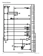
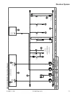
Page 12: ... 1 J1 10 10 J2 J2 5 5 J2 J2 J2 J2 6 2 J 6 J2 9 9 J1 J1 3 3 J1 J1 16 16 J2 J2 3 3 J1 J1 9 9 J2 J2 2 2 0318S11 M ALT P 0319 20 0318 20 0320A02 0318 17 050 0320G03 Vbat Vbat 30 31B ECU 0319E01 0319 01 0320G06 B B 1 2 0320F06 10A 1 2 0320F06 30A 0319 01 0320L07 30 0320L09 0320L10 0320L11 0320Q12 30 0 24W X1 X2 ROUGE 12V 31 0319 01 0524 0318 15 0320L19 A J H A B B B B C C C C D E F G G I K L G A Batter...

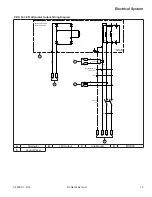
Page 13: ...mm GENERATOR BOBINAGE AUXILIAIRE AUXILIARY WINDING 6mm SILICABLE CSP Classe 5 Bleu 12 0321 01 30 0321 02 31A L3 0317 12 0317 13 0317 17 0317 17 R1 S1 S2 S1 V J 0321 01 P1 P2 S1 S2 0315T18 0321 01 N 0321 01 W1 U2 3 4 1 2 3 4 0315Q18 50A R2 R1 0321 01 V1 V2 2 1 S1 S2 U1 W2 A Alternator B 12V Output C Idle Module D MODYS E Control Panel ...

Page 14: ...747 S BULGIN 31613019004 ref bouchon PX0733 BULGIN 31613134303 X1 ref WAG273105 31613566201 C3 ref boîtier mâle 350766 1 AMP ref contacts femelles 350536 1 AMP 31C 31A 31 31B 0317 16 MODYS 0317E02 0318 01 BM 1 BM 2 1 2 0317F04 5x20 2A 30 30A BM 6 31A 30A 505 31 0319 20 BM 8 4 BM 10 0315 17 S1 BM 11 0315 17 R1 R1 S1 0318 19 0318 19 PLATINE DE RALENTI 0317E15 0318 14 0318 04 14 11 S3 080 080B 0317 0...

Page 15: ...S 300mA MAX MODYS output 300mA MAX MODYS 0317E02 0317 02 0317 20 0317 20 30 31B 86 85 0318KA02 12V BM 3 80 31B 0318 08 080 86 85 0318KA04 12V 0317 16 31B 30 86 85 0318KA05 12V 524 31B 86 85 0318KA06 12V BM 4 50 31B 080 30 10A 87 30 0318KA02 0318 02 30 080 0318 03 30 0319 05 080 30 080 3 4 0318S09 NOIR 1 2 30 080B 30 0319 06 080 30 87a 87 0318KA04 0318 04 X2 X1 0318H13 BLANC 12V 080A 31B 30 PLATINE...

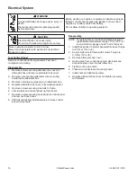
Page 16: ...move back panel 8 After disconnecting individual wires remove control panel components Reassembly NOTE To replace wires use heat resistant type wires permissible temperature range 75 C 167 F or over and same gauge of wire that is removed 1 Install back panel to control panel with screws Torque to 9 0 N m 79 in lb 2 Secure side rails to frame with screws Torque to 9 0 N m 79 in lb 3 Remove alternat...

Page 17: ...hield F Battery G Battery Bracket H Carbon Filter I Pipe Union J Alternator Box Cover K Alternator Box L Control Panel M Carbon Canister Strap N Carbon Canister Bracket O Oxygen Sensor Connector P Alternator Shield Q Fuel Hose R Side Rail S Fuel Filter T Carbon Canister Hose Disassembly Inspection and Service 17 34 690 01 8 16 KohlerPower com ...

Page 18: ... 2 Remove nuts securing alternator wires to wiring board inside alternator box 3 Remove nut retaining pipe union to alternator box 4 Replace alternator box cover to its original position WARNING Before working on engine or equipment disable engine as follows 1 Disconnect spark plug lead s 2 Disconnect negative battery cable from battery Do not allow children to operate generator Accidental Starts ...

Page 19: ...rvicing engine or alternator 1 Remove screws securing side rails to frame 2 Lift side rails and control panel up from frame Remove Carbon Canister NOTE Removal of carbon canister from side rail is not necessary unless either require service 1 Remove screws securing carbon canister strap around carbon canister 2 Remove carbon canister 3 Remove screws securing carbon canister bracket to side rail PR...

Page 20: ...ove engine and alternator as a unit follow next few steps otherwise continue to Remove Stator Frame 1 Remove nuts securing engine mounts 2 Remove nut securing alternator mount 3 Lift engine and alternator off frame PRO 12 3 EFI Engine and Alternator A B D C A Frame B Engine C Alternator Mount D Engine Mount Disassembly Inspection and Service 20 34 690 01 8 16 KohlerPower com ...

Page 21: ...frame off rotor Stator is very heavy Using a hoist or hydraulic lift will make removal easier 3 Inspect parts for cracks Replace if cracked Remove Rotor 1 Loosen through bolt but do not remove it 2 Place a wooden block or similar material under rotor to support weight as rotor is removed 3 With a rubber mallet tap rotor a few times Rotor should break free from engine shaft Remove through bolt and ...

Page 22: ...d to specifications 1 Place stator and frame on work surface with end cover down 2 Gently guide rotor into stator aligning bearing with bearing recess in back side of frame 3 Install alternator to front cover with screws and washers Using a hoist or hydraulic lift will make installation easier Torque screws to 21 0 N m 186 in lb 4 Install through bolt and torque to 21 0 N m 186 in lb PRO 12 3 EFI ...

Page 23: ...rnator mount 2 Install nuts securing mounts and torque to 9 9 N m 87 in lb PRO 12 3 EFI Engine and Alternator A B D C A Frame B Engine C Alternator Mount D Engine Mount PRO 12 3 EFI Control Panel Side Rails A B B C A Back Panel B Side Rail C Control Panel Install Control Panel to Side Rails 1 Install control panel to side rails with screws Torque to 9 0 N m 79 in lb 2 Install back panel to control...

Page 24: ...e Install Muffler Shiel NOTE It may be necessary to install nuts and screws loosely to align all holes before torquing 1 Install muffler shield over muffler and secure with nuts to exhaust studs Torque to 27 8 N m 246 in lb 2 Secure muffler shield to muffler with screws Torque to 9 0 N m 79 in lb 3 Install alternator shields to muffler shield and secure with screws Torque to 9 0 N m 79 in lb 4 Sec...

Page 25: ...ion Do not start engine near spilled fuel Never use fuel as a cleaning agent WARNING High Pressure Fluids can puncture skin and cause severe injury or death Do not work on fuel system without proper training or safety equipment Fluid puncture injuries are highly toxic and hazardous If an injury occurs seek immediate medical attention PRO 12 3 EFI Fuel Tank B A D E C A G F D A Fuel Tank B Screw C R...

Page 26: ...alternator box 3 Tighten nut to pipe union 4 Place wire connectors onto wiring board following instructions written in disassembly 5 Install nuts and tighten securely 6 Replace alternator box cover and tighten with screws Generator is now completely reassembled Before starting or operating engine be sure to follow steps below 1 Make sure all hardware is tightened securely 2 Turn on fuel supply 3 I...

Page 27: ...27 34 690 01 8 16 KohlerPower com ...

Page 28: ... 2014 2016 by Kohler Co All rights reserved 34 690 01 8 16a KohlerPower com ...

Reviews: