background image

UPS412-01-01 Kohler PW 5000/TP User Manual Dated 17-11-11

4-1

4

Operation

4.1

Commissioning

The Kohler PW 5000/TP UPS is a high quality electronic machine that must be commissioned by a fully
trained and authorised Kohler Uninterruptible Power field service engineer before being put into use.

Commissioning the UPS involves connecting the UPS battery, checking the electrical installation and
operating environment of the UPS, performing a controlled start-up and testing of the UPS system, and
customer training.

4.2

Control Panel

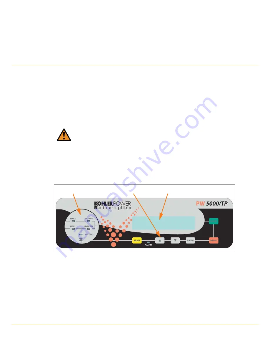
The user-friendly control panel is composed of three parts:

• Power Management Display (PMD)
• Mimic LED Indicators
• Operating keys

Figure 4.1   Control Panel

4.2.1  Power Management Display (PMD)

The 2 x 20 character LCD Power Management Display simplifies communication with the UPS and also
provides UPS monitoring information 

(See paragraph 4.3)

.

The menu driven LCD enables the access to: 

• The ‘Event register’
• Monitoring the input and output voltage, current, frequency & power
• Monitoring battery run time
• Perform commands such as UPS start-up and shut-down, Load transfer from INVERTER to BYPASS

and vice-versa

WARNING: 

Any Kohler PW 5000/TP UPS system not commissioned by a Kohler

Uninterruptible Power field service engineer must be considered an electrical hazard, and
Kohler Uninterruptible Power accepts no responsibility for its safe operation or the safety of
any personnel. Additionally, the manufacturer's warranty is immediately invalidated if the UPS
is put into use before it has been correctly commissioned.

Power Management Display (PMD)

Mimic LED Indicators

Operating Keys

Summary of Contents for PW 5000/TP

Page 1: ...Pioneering solutions for total power protection Kohler PW 5000 TP User Manual ...

Page 2: ......

Page 3: ...DATE REVISION SUMMARY 1 0 06 07 11 Initial issue 1 1 14 09 11 Major changes to Chapter 3 plus other general book wide updates 1 2 31 10 11 General corrections and layout update prior to initial issue 1 3 17 11 11 Update model nomenclature and general typographical error corrections ...

Page 4: ...asy to understand manual and will therefore assume no responsibility nor liability for direct indirect or accidental personal or material damage due to any misinterpretation of or accidental mistakes in this manual 2011 Kohler Uninterruptible Power This manual may not be copied nor reproduced without written permission of Kohler Uninterruptible Power ...

Page 5: ...3 1 3 2 2 Unpacking the UPS 3 2 3 2 3 Batteries 3 2 3 3 Storage 3 3 3 3 1 UPS storage 3 3 3 3 2 Battery 3 3 3 4 Positioning 3 3 3 4 1 Planning the installation 3 3 3 5 UPS Power Cabling 3 5 3 5 1 General requirements preparation and planning 3 5 3 6 Connecting the UPS input supply 3 13 3 6 1 Safety notes 3 13 3 6 2 Preparation for the input cabling 3 13 3 6 3 Connecting the UPS input power cables ...

Page 6: ... 5 4 3 6 UPS Data menu screen 4 5 4 3 7 Set up User menu screen 4 6 4 3 8 Set Up Service menu screen 4 6 4 4 Operating Modes 4 7 4 4 1 On Line Inverter mode 4 7 4 4 2 Bypass Line Interactive mode 4 7 4 4 3 Maintenance Bypass Mode 4 8 4 4 4 Multi module configuration concept 4 9 4 5 Operating Instructions 4 10 4 5 1 Transfer to Maintenance Bypass Mode 4 10 4 5 2 Starting the UPS system from the Mai...

Page 7: ... is UPS Management important 7 4 7 5 2 WAVEMON Shutdown and Monitoring Software 7 4 7 6 SNMP CARD ADAPTOR For Network Management Remote Monitoring 7 5 7 7 Modem Ethernet card PowerREPORTER management software 7 7 8 Specifications 8 1 Mechanical 8 1 8 2 Input Characteristics 8 2 8 3 Output Characteristics 8 2 8 4 Battery Characteristics 8 3 8 5 Environmental 8 3 8 6 Heat Dissipation With Non Linear...

Page 8: ...IV UPS412 01 01 Kohler PW 5000 TP User Manual Dated 17 11 11 ...

Page 9: ...e safety instructions and hazard warnings contained in this manual are read and fully understood WARNING High leakage current Ensure that the UPS has been correctly earthed before you connect the mains power supply WARNING This UPS must not be started up or put into use without having first been commissioned by a fully trained engineer authorised by the manufacturer WARNING All servicing must be p...

Page 10: ...1 Safety 1 2 UPS412 01 01 Kohler PW 5000 TP User Manual Dated 17 11 11 ...

Page 11: ...cialises in the design building installation and maintenance of Uninterruptible Power Systems This compact and powerful UPS is just one example of our wide range of state of the art power protection devices and will provide your critical equipment with a steady and reliable power supply for many years The criteria and methods which are used in the design manufacture and maintenance of Uninterrupti...

Page 12: ...t equipment etc No resonance with power factor correction capacitors 2 3 2 Flexible battery management This equipment employs a flexible battery management which avoids premature deterioration of battery life by advanced management of battery charging and preventive failure diagnostics The major benefits are AC ripple free battery charging due to a dc dc charger separated from the rectifier and in...

Page 13: ...ability of Kohler Uninterruptible Power is adequately protected under the circumstances 2 5 Extended Warranty The Standard Warranty may be enhanced by protecting the UPS with an Extended Warranty Agreement maintenance contract An Extended Warranty Agreement enhances the standard warranty by providing the following Regular preventative maintenance inspections Guaranteed speed of response to operati...

Page 14: ...g kohler com Regional Office South East Asia Kohler Uninterruptible Power 7 Jurong Pier Singapore 619159 Tel 65 63020708 Name Job Title Company Address Post Code Tel Fax E mail Please contact me to discuss Extended Warranty options for my Kohler PW 5000 TP UPS Extended warranty options for my UPS System as below Manufacturer Model Nº Rating kVA Replacement Batteries Other please specify Fax to 65 ...

Page 15: ... operations described in this section must be performed by authorised electricians or suitably qualified personnel Kohler Uninterruptible Power will take no responsibility for any personal or material damage caused by incorrect cabling or operations or activities which are not carried out in strict accordance with the instructions contained in this manual CAUTION When off loading the UPS always ke...

Page 16: ...nternal door corresponds to the purchased material mentioned in the goods delivery note 3 2 3 Batteries The batteries connected to the UPS are usually of a sealed maintenance free design The batteries can be mounted either within the UPS in an external battery cabinet or on a bespoke battery rack depending on the required autonomy time and paralleling arrangement For optimum reliability a separate...

Page 17: ...ack to enable cooling airflow Allow a minimum of 200mm clearance at the back of the cabinet Suitable ventilation airflow not exceeding 40 C must be provided See Figure 3 2 4 All parts of the UPS requiring access for maintenance servicing and user operation are accessible from the front and rear Reserve a minimum of 900mm space at the front of the UPS cabinet 5 An ambient temperature of 20 C is rec...

Page 18: ...oad W 120 150 150 170 250 300 350 Cabinet A Cabinet B Cabinet C Batt Cab C Dimensions WxHxD mm 345x720x710 345x1045x710 440x1420x910 480x1420x940 Maintenance Service Accessibility Top rear front left and right side Top front left and right side Positioning Min 200mm rear space required for ventilation Input and Output Power Cabling From the bottom at the rear From the bottom at the front UPS Z Fro...

Page 19: ...dedicated bypass supply See Figure 3 4 Figure 3 4 identifies the UPS input output cabling requirements and provides information regarding the necessary fuse and cable ratings and cable sizing Figures 3 6 3 7 show details of the power terminal connections within the UPS including connection sizes and recommended tightening torque This illustration shows that the UPS unit requires the following powe...

Page 20: ...1 11 Input neutral grounding Figure 3 3 Input neutral grounding Key Point Input neutral is required to operate the rectifier In TN S systems no 4 pole input switches or circuit breakers should be used During battery operation the neutral must always be grounded 0V 230V UPS ...

Page 21: ...IEC 60950 1 2001 2 The fuse and cable rating details in the above tables are a recommendation only 3 The UPS must be installed to prescribed IEC or local regulations 4 External DC Cables and Battery fuses are bespoke to the installation Power kVA Fuse A Agl CB A Cable A mm Cable D mm 10 3 x 20 5 x 2 5 5 x 2 5 15 3 x 32 5 x 4 0 5 x 4 0 20 3 x 40 5 x 6 0 5 x 6 0 25 3 x 40 5 x 6 0 5 x 6 0 30 3 x 63 5...

Page 22: ... board to each UPS cabinet should be of equal length Similarly the UPS output cables to the output distribution board should be of equal length See Figure 3 5 Figure 3 5 Cable lengths for multi cabinet configurations assuming a dual input supply UPS 1 UPS 2 UPS 3 UPS 4 UPS 1 UPS 2 UPS 3 UPS 4 Recommended cable configurations The cable configuration below is not recommended Bypass Feed Rectifier Fe...

Page 23: ...dation only The UPS must be installed to prescribed IEC or local regulations 10kVA 25kVA Cabinets A B Power Connections Single input feed 10kVA 25kVA Cabinets A B Power Connections Dual input feed For models in this power range the external power connections are made to a row of terminals located on the UPS Filter Board which is accessible from the rear of the UPS module Note that the Single Input...

Page 24: ...rnal power connections are made to a row of terminals blocks mounted on a rail on the front of the UPS module Note that the Single Input configuration requires three links to be fitted between the input and bypass supply connections as shown in the above illustration This is the standard configuration set when leaving the factory unless a dual input configuration is specified Cabinet C Single inpu...

Page 25: ...D D D D D 3L1 3L2 3L3 3N PE3 OUTPUT LOAD SUPPLY Rectifier SINGLE INPUT FEED Notes 1 Fuse and Cable recommendations to IEC 60950 1 2001 2 The fuse and cable rating details in the above tables are a recommendation only 3 The UPS must be installed to prescribed IEC or local regulations 4 External DC Cables and Battery fuses are bespoke to the installation Power kVA Fuse A Agl CB A Cable A mm Cable D ...

Page 26: ... 2L3 2N PE2 DUAL INPUT FEED Notes 1 Fuse and Cable recommendations to IEC 60950 1 2001 2 The fuse and cable rating details in the above tables are a recommendation only 3 The UPS must be installed to prescribed IEC or local regulations 4 External DC Cables and Battery fuses are bespoke to the installation Power kVA Fuse B Agl CB A Cable B mm Fuse C Agl CB A Cable C mm Cable D mm 10 3 x 20 5 x 2 5 ...

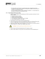
Page 27: ...uring the UPS installation ensure that the connections are performed under the following conditions a No mains voltage is present b Loads are shut down and disconnected c The UPS is shut down and voltage free d The UPS Maintenance Bypass Isolator IA1 is OFF e The UPS Output Parallel Isolator IA2 is OFF 2 Gain access to the UPS power terminals 3 Connect the earth cable from the LV Distribution Boar...

Page 28: ...place 3 7 Connecting the UPS output 3 7 1 Safety notes Please ensure you read and understand the following safety notes before you begin the UPS electrical installation 1 All operations detailed in this section must be performed by an authorised electrician or qualified personnel 2 Once the electrical installation is completed the initial UPS start up must be performed by qualified personnel autho...

Page 29: ...e is present b All loads are shut down and isolated c The UPS is shut down and voltage free d The UPS Maintenance Bypass Isolator IA1 is OFF OPEN e The UPS Parallel Isolator IA2 is OFF OPEN 2 Gain internal access to the UPS and remove the UPS terminal cover 3 Connect the protective earth cable from the Load Distribution Board to the protective earth PE busbar in the UPS located adjacent to the pow...

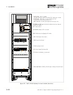
Page 30: ...ot for optional Modem Ethernet card ONLY JD1 RS232 Interface UPS to computer X1 Customer inputs JR1 RS485 on RJ45 port Interface for Multidrop connection between several UPS cabinets SW1 9 Multi cabinet configuration DIP switch JD8 Parallel Bus connector Multi module system option only FA3 Battery fused isolator FA1 Rectifier input fused isolator FA2 Bypass fused isolator IA2 Output parallel isola...

Page 31: ...t for optional Modem Ethernet card ONLY JD1 RS232 Interface UPS to computer X1 Customer inputs JR1 RS485 on RJ45 port Interface for Multidrop connection between several UPS cabinets SW1 9 Multi cabinet configuration DIP switch JD8 Parallel Bus connector Multi module system option only FA3 Battery fused isolator FA1 Rectifier input fused isolator FA2 Bypass fused isolator IA2 Output parallel isolat...

Page 32: ...ot for optional Modem Ethernet card ONLY JD1 RS232 Interface UPS to computer X1 Customer inputs JR1 RS485 on RJ45 port Interface for Multidrop connection between several UPS cabinets SW1 9 Multi cabinet configuration DIP switch JD8 Parallel Bus connector Multi module system option only F1 Battery fused isolator FA1 Rectifier input fused isolator FA2 Bypass fused isolator IA2 Output parallel isolat...

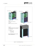
Page 33: ...re To protect personnel during battery installation the connections must be made under the following conditions Mains voltage must be disconnected from the UPS All loads must be disconnected The UPS and the external battery terminals must be voltage free 1 The UPS must be totally shut down and power free Ensure the mains and bypass supply is isolated at the UPS input distribution board 2 Ensure th...

Page 34: ...m of 96 2x48 x 7 9Ah blocks Cabinet C Contains a number of battery shelves that can be adjusted removed to cater for different sized battery blocks For example 48 x 28Ah blocks 96 x 9Ah blocks 144 x 9Ah blocks Note All installations must use an even number of battery blocks Cabinet A Cabinet B Cabinet C Batt Location Batt Location Batt Location Batt Location Batt Location ...

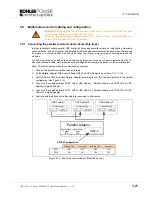
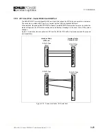
Page 35: ...allel Adaptor according to the UPS cabinet s position in the parallel configuration See Figure 3 14 4 Connect a Bus cable between PORT JD6 of UPS Cabinet 1 Parallel Adaptor and PORT JD5 of UPS Cabinet 2 Parallel Adaptor 5 Connect a Bus cable between PORT JD6 of UPS Cabinet 2 Parallel Adaptor and PORT JD5 of UPS Cabinet 3 Parallel Adaptor 6 Continue with the above until a Bus cable is connected to ...

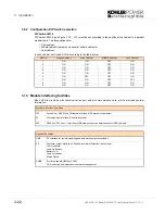
Page 36: ...SW1 9 Single Cabinet First Cabinet Middle Cabinet Last Cabinet 1 ON ON OFF ON 2 ON ON OFF ON 3 ON ON OFF ON 4 ON ON OFF ON 5 ON ON OFF ON 6 ON OFF OFF ON 7 ON ON OFF OFF 8 ON ON OFF ON 9 ON ON OFF ON Standard Interface Facilities JD1 Smart Port RS232 Sub D9 female interface UPS system to computer X1 Customer input interface Phoenix terminals JR1 RS485 on RJ 45 port Interface for Multidrop connecti...

Page 37: ...tional SMART PORT software PowerREPORTER allows the computer to monitor the mains voltage and the UPS status continuously and display a message in the event of any UPS system changes Figure 3 15 and show the connection to a PC from the UPS for PC s with a 9 pin serial port and 25 pin serial port respectively Figure 3 15 Connector Cable PC Serial Port 1 2 3 4 5 9 1 2 3 4 5 9 1 2 3 4 5 9 1 2 3 4 5 6...

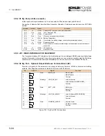
Page 38: ...rs AS400 or Automation building systems All voltage free contacts are rated 60 VAC max and 500 mA max Figure 3 16 Dry Port X2 Connections Terminal Contact Signal Function X1 1 In 12Vdc Customer IN 1 default as Generator Operation X1 2 Gnd Gnd NC Generator ON X1 3 In 12Vdc Customer IN 2 X1 4 Gnd Gnd Function on request to be defined X1 5 In 3 3Vdc Battery Temperature X1 6 Gnd Gnd If connected the b...

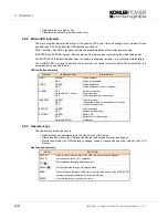
Page 39: ...ement Display PMD The 2 x 20 character LCD Power Management Display simplifies communication with the UPS and also provides UPS monitoring information See paragraph 4 3 The menu driven LCD enables the access to The Event register Monitoring the input and output voltage current frequency power Monitoring battery run time Perform commands such as UPS start up and shut down Load transfer from INVERTE...

Page 40: ...up and shut down the UPS and transfer the load between inverter and bypass Monitor and display the UPS operating voltages currents frequencies and other values on the LCD display Key function summary Indicator Indicator Status Interpretation LINE 1 GREEN RED Mains available Mains not available LINE 2 GREEN RED Mains bypass OK Mains bypass not OK or not present ALARM OFF Flashing RED buzzer RED No ...

Page 41: ... chain The position of a module in a multi module configuration is set by DIP Switch SW1 9 see paragraph 3 9 2 on page 3 22 First First UPS module in the parallel configuration chain Middle UPS module in the middle of the parallel configuration chain there may be more than one middle UPS Last UPS module is last in the parallel configuration chain If a UPS is operating as a Single module then it is...

Page 42: ...graph 4 3 7 SET UP USER SET UP SERVICE 6 Password protected area for service engineer use only See paragraph 4 3 8 SET UP SERVICE DESCRIPTION LCD DISPLAY 1 Logging Control a log of the last 99 events is stored in the Power Management Display 01 05 10 08 14 38 56 LOAD TO INV 2 Every stored event is identified with a sequential number and time stamp 02 05 10 08 14 38 59 LOAD TO BYP 3 By pressing ENT...

Page 43: ... Output Power all three phases APPARENT POWER KVA 00 00 00 00 00 00 14 Output Power all three phases OUTPUT POWER 00 00 00 00 00 00 15 Battery capacity BATT CAPACITY 00 00 DESCRIPTION LCD DISPLAY 1 Transfer Load to inverter LOAD TO INVERTER LOAD TO BYPASS 2 Transfer Load to bypass LOAD TO BYPASS PERFORM BATT TEST 3 Battery Test PERFORM BATT TEST DESCRIPTION LCD DISPLAY 1 These general UPS Data are...

Page 44: ...RIPTION LCD DISPLAY 1 Set up language SET LANGUAGE SET DATE AND TIME ENGLISH FRANCAIS DEUTCH DUTCH SPANISH POLISH PORTOGUESE 2 Set up Date and Time SET UP DATE TIME SET UP BATT TEST DD MM YY HH MM SS 3 Set up battery test SET UP BATT TEST SET UP GEN SET OPER DAY OF MONTH 1 31 HOUR OF DAY 0 23 REPETITIVE Y N YES NO 4 Set up operation with Gen Set SET GENERATOR OP BATT CHARGE LOCK YES NO BYPASS LOCK...

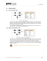
Page 45: ... Figure 4 3 Line Interactive Bypass Mode In the Bypass Line Interactive mode the load is supplied from the bypass mains LINE 2 and the static BYPASS In the event of a mains failure the load is automatically transferred to the inverter within 3 to 5 msec this is valid for single and parallel module systems The battery charger remains active in this mode Although this mode of operation offers greate...

Page 46: ...enance bypass circuit is provided by a single external circuit breaker that wraps around the entire UPS system For reasons of safety and sustaining the load during switchover the external maintenance bypass circuit breaker is normally interlocked with the UPS input mains supply circuit breaker at the mains distribution panel Switch IA1 Effect ON Maintenance Bypass Switch Closed Load on bypass main...

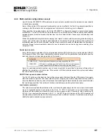
Page 47: ...e module s output from the parallel bus and therefore from the load and there is no power being provided by the inverter Note In a redundant module system one or more module s is permitted to be taken off line without affecting the remaining on line modules If the number of off line modules exceeds the system redundancy the load is transferred to bypass ON OFF Start up and shutdown buttons The ON ...

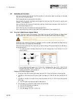
Page 48: ...is procedure check and confirm the following UPS system status on all cabinets in a multi module system The mimic panel LED indications should be as per the following table on all cabinets in a multi module system The LCD panel should display LOAD PROTECTED If anything other than LOAD PROTECTED is displayed then press the RESET button and if LOAD PROTECTED is still not displayed there is a problem...

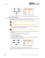
Page 49: ...n for example if required for maintenance testing using the following procedure Note Carry out the following procedure on each module in a parallel system 7 On the UPS control panel simultaneously press both ON OFF buttons a The LCD panel will indicate LOAD OFF SUPPLY FAILURE 8 Open the battery fuse isolator a Open FA3 F1 if using internal batteries b If using external batteries open the battery f...

Page 50: ...The UPS mimic panel LINE 1 LED will be permanent green b The BATTERY LED will be flashing green c The LCD display will indicate LOAD OFF SUPPLY FAILURE 3 Close the Parallel Isolator switch IA2 and check that the PARALLEL SW CLOSED message is shown on the LCD display 4 On the UPS mimic panel press and release both ON OFF buttons simultaneously and wait approximately 60 seconds a The UPS module will...

Page 51: ...s the RESET button to cancel the audible alarm on all modules a The LCD display s will now indicate LOAD NOT PROTECTED Transferring the load to the inverter 9 On the Control Panel of any one module in a multi module system a Press the UP key once to access the menu system b Use the UP DOWN keys to move the cursor so that it is adjacent to COMMANDS and then press the ENTER key c Use the UP DOWN key...

Page 52: ...Open the battery fuse isolator a Open FA3 F1 if using internal batteries b If using external batteries open the battery fuses isolator on the associated battery cabinet rack 5 Open the module s Parallel Isolator switch IA2 6 Open the Bypass Line fuse holder FA2 and the Rectifier Line fuse holder FA1 7 Open the UPS Input and Bypass supply fused isolators or breakers in the building power distributi...

Page 53: ... supply isolator at the LV switchboard a The LINE 1 indicator will illuminate green b The LCD display will indicate LOAD OFF SUPPLY FAILURE Note If necessary press the RESET button to obtain this display indication 3 Close the battery fuse isolator a Close FA3 F1 if using internal batteries b If using external batteries close the battery fuses isolator on the associated battery cabinet rack 4 Simu...

Page 54: ...tor switch IA2 3 In the UPS Cabinet open the Input supply and Bypass supply fused isolators FA1 and FA2 4 Open the battery fuse isolator a Open FA3 F1 if using internal batteries b If using external batteries open the battery fuses isolator on the associated battery cabinet rack 5 Open the UPS input supply isolator and UPS output isolator on the LV Switchboard 6 The UPS module is now totally shut ...

Page 55: ...field service engineer will attach a service record book to the front of the UPS which will be used to log the full service history of the UPS Preventative maintenance inspections involve working inside the UPS which contains hazardous AC and DC voltages During a preventative maintenance inspection the field service engineer will carry out the following checks Site environment conditions Integrity...

Page 56: ...st takes approximately 3 minutes and should be performed only if There are no alarm conditions The battery is fully charged The battery test procedure can be performed from the UPS front panel and can be carried out independently of the operating mode Off line or On line and whether or not the load is connected ...

Page 57: ...ault identification and rectification information is given on the following pages 6 2 Menu Commands Event Log Measurements A detailed description of the Menu Commands Event Log and Measurements that can be operated and displayed on the LCD can be found in Section 4 6 2 1 Event Log Screen As you step through the event memory make a separate note of each alarm condition as this will assist in the id...

Page 58: ...tions and repair as required OVERLOAD Load exceeds the UPS rated power Identify which piece of equipment is causing the overload and remove it from the UPS Do not connect laser printers photocopiers electric heaters kettles etc to the UPS OVERTEMPERATURE UPS temperature has exceeded the allowed value Check the ambient temperature of the UPS is less than 30 C If the ambient temperature is normal ca...

Page 59: ...and X1 8 on the communications board which opens to operate the emergency stop sequence Note Usually the remote emergency stop function is disabled and it should be activated by a hardware code on the SETUP SERVICE menu Please contact your distributor to enable this operation To allow removal maintenance or testing of any remote emergency stop facility without disturbing the normal operation of th...

Page 60: ...e UPS input power When used this facility inhibits the operation of the battery charger and or static bypass while the UPS is being supplied from a standby generator See Set up User menu screen in section 4 3 7 1 Use a screened cable with 1 pair section of wires 0 6 mm2 and maximum length of 100 m 2 Connect the cable as shown in Figure 7 2 Figure 7 2 Generator ON Connection X1 X1 1 X1 2 Generator ...

Page 61: ...d 17 11 11 7 3 7 Options 7 4 Temperature sensor for temperature dependant battery charging A temperature sensor can be used to vary the battery charging voltage depending upon the battery temperature X1 X1 5 X1 6 Temp Sensor Battery Temperature Port ...

Page 62: ...or computer systems 7 5 2 WAVEMON Shutdown and Monitoring Software WAVEMON is an external monitoring and shutdown software application that is designed to operate with many of Kohler Uninterruptible Power UPS products The package comprises a software installation CD suitable for most server operating systems a standard cable set and a user manual The WAVEMON system can monitor the dry port relay c...

Page 63: ...ply Every alarm on any unit is immediately notified but a reaction to a serious fault is introduced only when the minimum number of UPS Modules necessary to supply the load exhibits an alarm situation The real battery autonomy time of the whole parallel system is computed continuously Maintenance on a redundant unit may be executed without affecting the management system supervisor The Kohler PW 5...

Page 64: ...d to monitor any device in the network and can be used utilising the RCCMD send function for an automatic network wide shut down or informing connected users The shut down procedure can be initiated from the remaining time downtime or as countdown timer from the beginning of the alarm A shut down is therefore possible without extra input from the operator but fully software controlled For detailed...

Page 65: ...s Redundant and secure communication Alarm acknowledgment Priority driven Management with escalation Comprehensive Management System Reception and management of alarm calls from UPS Storage of UPS Data in a database exportable in a CSV format for easy handling in Excel Unlimited number of UPS that can be managed User administration with passwords and permission level Administration of Log file Dat...

Page 66: ...7 Options 7 8 UPS412 01 01 Kohler PW 5000 TP User Manual Dated 17 11 11 ...

Page 67: ... 10 15 20 25 WITHOUT BATTERY ENCLOSURE Dimensions WxHxD mm 345 x 1045 x 710 Weight without battery kg 88 90 92 94 Weight with 96x7Ah battery kg 328 330 332 334 Weight with standard packaging kg 5 Colour Graphite grey RAL 7024 Module Rating kVA 25 30 40 50 WITHOUT BATTERY ENCLOSURE Dimensions WxHxD mm 440 x 1420 x 910 Weight without battery kg 9Ah 28Ah 151 135 9Ah 28Ah 160 145 9Ah 28Ah 165 150 9Ah ...

Page 68: ...rated output power and discharged battery output pf 0 9 A 15 2 22 8 30 4 37 9 45 5 60 7 75 9 Module Rating kVA 10 15 20 25 30 40 50 Output Rated Power KW 9 13 5 18 22 5 27 36 45 Output Current In p f 0 9 400 V A 13 0 19 5 26 0 32 5 39 0 52 0 65 0 Output Current In p f 1 0 400 V A 14 4 21 7 28 9 36 1 43 3 57 7 72 2 Output Rated Voltage V 3x380 220V or 3x400 230V or 3x415 240V Output Voltage Stabili...

Page 69: ...L MODULES Metres above sea level m ft De Rating Factor for Power 1500 4850 0 95 2000 6600 0 91 2500 8250 0 86 3000 9900 0 82 Relative Air humidity Max 95 non condensing Positional Clearances Front A minimum of 900mm should be allowed for free passage Side 600mm left and right side access is required for service Rear A minimum of 200mm is required for cooling air circulation and the unit should be ...

Page 70: ...Modules Power Management Display PMD LCD display RS232 on Sub D9 port For monitoring and integration in network management Customer Interfaces Inputs DRY PORTS 1 Remote Shut down EMERGENCY OFF Normally closed 1 GEN ON Normally open 1 Programmable Customer s Inputs Normally open 1 Temp Sensor for Battery Control 1 12Vdc source max 250mA RJ45 port For multidrop purpose optional Relay card USB Includ...

Page 71: ...950 1 2001 2 The fuse and cable rating details in the above tables are a recommendation only 3 The UPS must be installed to prescribed IEC or local regulations 4 External DC Cables and Battery fuses are bespoke to the installation Power kVA Fuse A Agl CB A Cable A mm Cable D mm 10 3 x 20 5 x 2 5 5 x 2 5 15 3 x 32 5 x 4 0 5 x 4 0 20 3 x 40 5 x 6 0 5 x 6 0 25 3 x 40 5 x 6 0 5 x 6 0 30 3 x 63 5 x 10 ...

Page 72: ...8 Specifications 8 6 UPS412 01 01 Kohler PW 5000 TP User Manual Dated 17 11 11 ...

Reviews: