UPS412-01-01 Kohler PW 5000/TP User Manual Dated 17-11-11
4-15
4: Operation
8.
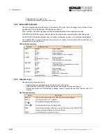
The UPS is now voltage free.
4.5.4 Individual module start/stop procedure
If a multi-module system is designed with built-in redundancy it is possible to stop and start one module
without affecting the operational status of the overall system – e.g. one module can be taken off-line for
servicing whilst the remaining modules maintain the protected load supply.
Module start-up:
Use this procedure to start a module and connect it to a multi-module system.
This procedure assumes the following initial conditions:
• UPS input isolators are open on the building’s LV supply switchboard
• The fused battery isolator(s) are open
• In the UPS cabinet, the fused isolators FA1, FA2 and the parallel isolator (IA2) are open
1.
In the UPS cabinet, close the Input supply and Bypass supply fused isolators FA1, FA2 and the Parallel
Isolator IA2.
2.
Close the UPS input supply isolator at the LV switchboard.
a)
The
LINE 1
indicator will illuminate green.
b)
The LCD display will indicate
LOAD OFF SUPPLY FAILURE
.
Note:
If necessary press the
RESET
button to obtain this display indication.
3.
Close the battery fuse/isolator.
a)
Close FA3/F1 if using internal batteries.
b)
If using external batteries close the battery fuses/isolator on the associated battery cabinet/rack.
4.
Simultaneously press the two
ON/OFF
push buttons on the UPS control panel.
a)
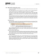
The UPS will run through an automated start-up sequence accompanied by the following indications:
LINE 2
LED lights red then changes to green.
INVERTER
LED lights green.
BATTERY
LED lights green (constant).
b)
LCD displays the
LOAD PROTECTED
message.
5.
The UPS module is now On Line and connected to the parallel system.
WARNING:
Allow 10 minutes for the internal DC capacitors to discharge before touching the
UPS internal components.
WARNING:
All the operations in this section must be performed by authorised and trained
personnel.
LINE 1
LINE 2
BY PASS
INVERTER
BATTERY
LOAD
LED
Colour
LINE 1
Green
LINE 2
Green
BY PASS
Off
INVERTER
Green
BATTERY
Green
Summary of Contents for PW 5000/TP
Page 1: ...Pioneering solutions for total power protection Kohler PW 5000 TP User Manual ...
Page 2: ......
Page 8: ...IV UPS412 01 01 Kohler PW 5000 TP User Manual Dated 17 11 11 ...
Page 10: ...1 Safety 1 2 UPS412 01 01 Kohler PW 5000 TP User Manual Dated 17 11 11 ...
Page 66: ...7 Options 7 8 UPS412 01 01 Kohler PW 5000 TP User Manual Dated 17 11 11 ...
Page 72: ...8 Specifications 8 6 UPS412 01 01 Kohler PW 5000 TP User Manual Dated 17 11 11 ...


