3: Installation
3-12
UPS306-01-00 PowerWAVE 9000 DPA User Manual Dated 01-06-2010
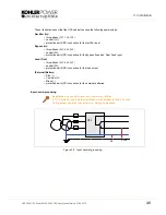
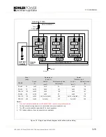
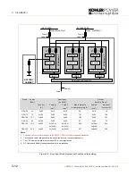
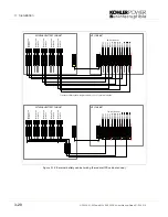
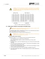
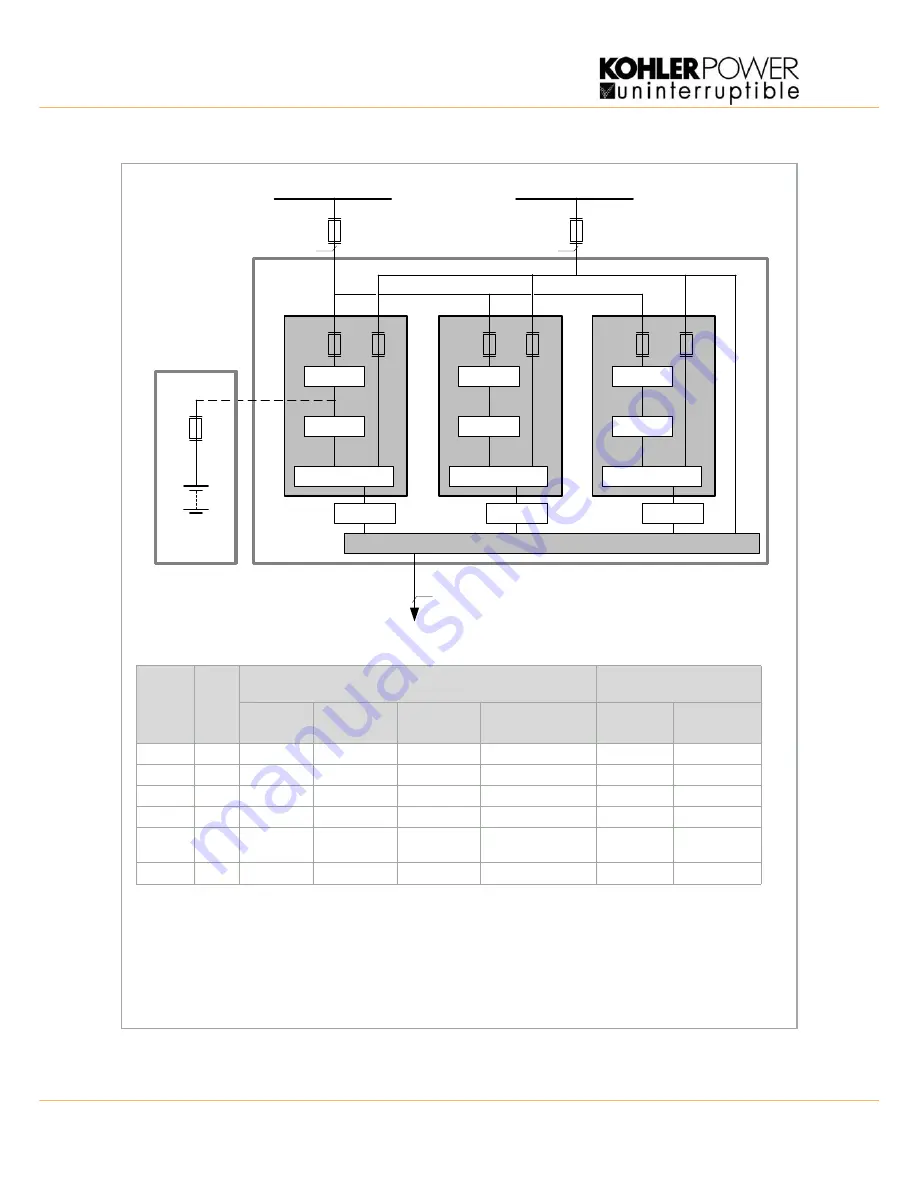
Figure 3.6 Dual input block diagram with cable and fuse sizing
Fuse B
Load
INPUT FEED
Mains (3x400/230V)
Cable D
Cable B
F1
F2
U
PS Modul
e
1
Static Switch
F1
F2
U
PS Modul
e
3
Rectifier
Inverter
Rectifier
Inverter
F1
F2
UPS Modul
es
2
Rectifier
Inverter
Maintenance Bypass IA1
Fuse C
Cable C
BYPASS FEED
Mains (3x400/230V)
Static Switch
Static Switch
BATTERY
CABINET
IA2-1
IA2-2
IA2-3
Notes:
1.
Fuse
and Cable recommendations to IEC 60950-1:2001 or locally recoginsed standards.
2.
The fuse and cable rating details in the above tables are a recommendation only.
3.
The UPS must be installed to prescribed IEC or local regulations.
4.
DC Cables and Battery fuses are bespoke to the installation.
Frame
Power
(kVA)
Dual Input
(3 x 400V)
Output
(3x400V, 0.8 pf)
Fuse B/C
(A)
Cable B
(mm
2
)
Cable C
(mm
2
)
Max Input with
battery charging (A)
Cable D
(mm
2
)
Nominal
Current (A)
DPA-25
25
3x63
5x10
4x10
34
5x10
36
DPA-75
75
3x125
5x50
4x50
101
5x50
108
DPA-125
125
3x225
5x95
4x95
169
5x95
181
DPA-50
80
3x100
5x25
4x25
67
5x25
72
DPA-150
150
3x250
5x120 or
5x(2x50)
4x120 or
4x(2x50)
202
5x120 or
5x(2x50)
218
DPA-250
250
3x400
5x(2x95)
4x(2x95)
337
5x(2x95)
362
Summary of Contents for PW 9000DPA
Page 1: ...User Manual Pioneering solutions for total power protection Kohler PW 9000DPA ...
Page 2: ......
Page 8: ...iv UPS306 01 00 PowerWAVE 9000 DPA User Manual Dated 01 06 2010 ...
Page 10: ...1 Safety 1 2 UPS306 01 00 PowerWAVE 9000 DPA User Manual Dated 01 06 2010 ...
Page 18: ...2 Description 2 8 UPS306 01 00 PowerWAVE 9000 DPA User Manual Dated 01 06 2010 ...
Page 76: ...7 Options 7 6 UPS306 01 00 PowerWAVE 9000 DPA User Manual Dated 01 06 2010 ...
Page 85: ...UPS306 01 00 PowerWAVE 9000 DPA User Manual Dated 01 06 2010 8 9 8 Specifications ...
Page 86: ...8 Specifications 8 10 UPS306 01 00 PowerWAVE 9000 DPA User Manual Dated 01 06 2010 ...


