background image

9

B. Install Ceramic Floor Rail

The Vintage Ceramic Floor Rail is for use with a free-
standing Vintage Bath. However, the bath must be
installed before the ceramic floor rails.

Please see Installation Instructions for properleg
adjustment procedure.

Also, it is recommended that the flooring and the
plumbing be completed before the installation of the
floor rail. The bath should be leveled at a height that
provides clearance between the top of the ceramic floor
rail and bottom of the bath.

CAUTION: The bath must be supported by
the cast iron legs, not the ceramic floor rails.

·

·

·

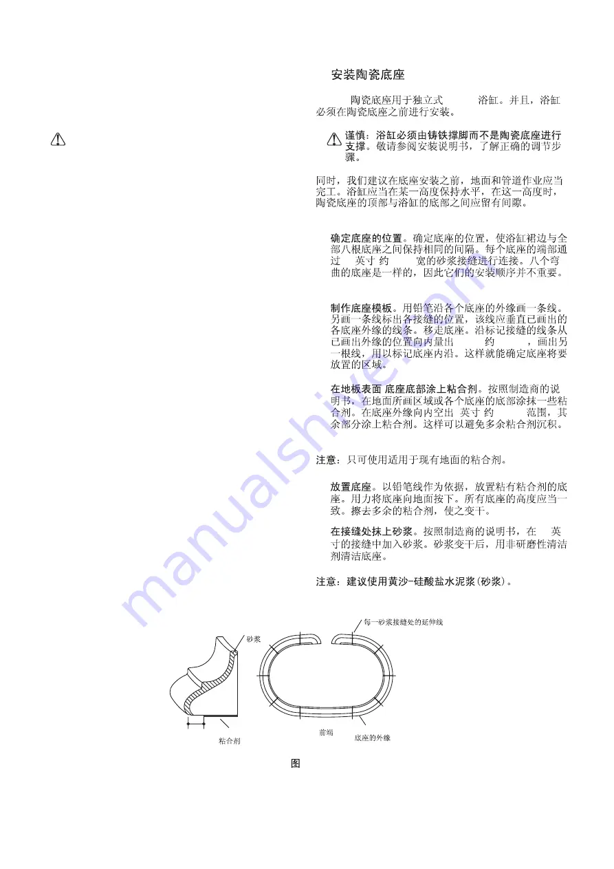
Position Floor Rails on Site.

Create Floor Rail Template.

Application of Adhesive to Floor Surface/Floor
Rail Bottom.

NOTE:

Position floor rails so

there is an equel space between bath skirt and all
eight floor rails. The ends of each floor rail are
connected by a 1/8 grout joint. The eight curved
floor rails are identical, so their order of installation
is not critical.

Trace the outside

edge of each floor rail with a pencil. Mark location of
joints with a line that extends beyond the traced
outside edge of each floor rial. Remove floor rails.
Measure in 3-3/4 from traced outside edge and
mark another line. This will establish the area in
which the floor rails will be located.

Per manufacturer

instructions, apply

adhesive to traced area on the floor or bottom
surface of each floor rail. Apply adhesive to within 1
of outside edge of floor rail. This will avoid excess
adhesive build up.

Use only adhesive that is appropriate for use

with existing flooring.

"

"

"

,

s

B.

Vintage

Vintage

1/8

(

3mm)

"(

95mm)

1

(

25mm)

!

!

!

3-3/4

/

Extended Line At Each Grout Joint

Outside Edge Of Floor Rail

Adhesive

Front

Grout

!

·

Set Floor Rails.

Using the pencilled lines as a guide,

set the floor rails with adhesive. Press floor rails
firmly to the floor. Height of all floor rails should be
consistent. Clean up excess adhesive and let dry.

"

Apply Grout to Joints.

NOTE: Send-Portland Cement Grout (sanded-grout)
is recommended.

Permanufacturer

instructions, apply sanded-grout to 1/8 grout joints.
When dry, clean floor rails with a non abrasive
cleaner.

,

s

!

!

1/8

1"(25.4mm)

Fig. #1

1

1023725-T01-A

Summary of Contents for Vintage K-700T

Page 1: ...under the feet This is the combined weight of the bath water and two bathers 2000 907 ANSI A112 19 1 BEFORE YOU BEGIN BEFORE YOU BEGIN 368 201419 Please read these instructions carefully to familiarize yourself with the required tools materials and installation sequences Follow the sections that pertain to your particular installation This will help you avoid costly mistakes In addition to proper ...

Page 2: ...n for free standing Adjustable feet Optional A Recommended K 7158T K 7159T K 1172T B 1118 610mm 1524 813mm 220Kg 381mm 310 B Product Information Fixture Basin area Top area Weight 1118 610mm 1524 813mm 220Kg Bathing Well Water depth 381mm 310L Capacity To Overflow Approximate measurements for comparison only Roughing In Notes Fixture dimensions are nominal and conform to toler ances in ANSI Standa...

Page 3: ...eet 2mm gap between the finished deck floor surface so the bath does not rest on the rim Use the template packed with the bath to carefully lay out and cut the rough deck material Make sure the drain location corresponds to the bath outlet Position the plumbing according to the roughing in information Cap the supplies and check for leaks Install the finished flooring and wall materials For all ins...

Page 4: ... Tube Assemble coupling nuts and tapered gaskets note proper position above on overflow tube and drain elbow For through the floor installations the threaded portion of the tee points toward the floor For above the floor installations the threaded portion of the tee points away from the drain elbow as shown above Align parts with the tee in the proper configuration for your installation Make sure ...

Page 5: ...rer instructions to the front side of the gasket putty will be between the gasket and the bath Align the overflow elbow with the overflow hole in the bath From inside the bath tighten the retainer nut to the overflow elbow Tighten all coupling nuts on the tee to secure the assembly Apply thread sealant tape to the tailpiece threads Thread the tailpiece onto the tee and tighten securely Make sure t...

Page 6: ...just Drain Stopper If adjustment is required remove the stopper assembly from the drain and loosen the jam nut below the stopper Turn the jam nut counterclockwise to raise the stopper or clockwise to lower the stopper Tighten the nut If sufficient clearance cannot be obtained by adjusting the stopper remove the lift rod assembly and loosen the locknut Rotate the turnbuckle counterclockwise to leng...

Page 7: ...he floor with the screws provided Position the bath so there is equal space between the bath skirt and the floor rail CAUTION Risk of personal injury Cast iron baths are extremely heavy Obtain sufficient help to carefully lift or move the bath Use at least four people to carefully lift the bath inside the floor rail Insert the dowels in the ends of the floor rail Apply silicone sealant to the end ...

Page 8: ... from the back or side move the bath in and out to shim it properly Verify that the bath is level across the top and along the drain side NOTE Do not use drywall plaster to support the bath Level By Fitting Metal Shims Under The Bath Feet H Install the Towel Bar Freestanding Installations Only Attach the two end brackets to the bath rim with the washers and bolts Carefully slide the two support br...

Page 9: ...tside edge of each floor rail with a pencil Mark location of joints with a line that extends beyond the traced outside edge of each floor rial Remove floor rails Measure in 3 3 4 from traced outside edge and mark another line This will establish the area in which the floor rails will be located Per manufacturer instructions apply adhesive to traced area on the floor or bottom surface of each floor...

Page 10: ...degrees the drain tube can be run into the wall before meeting the trap Install the legs according Fig 3 The leg mount attached to the bath sits atop the leg secured by the nut and bolt Height is varied by adjusting the bottom bolt as shown K 1172T K 1172T 2 3 4 70mm 3 1 2 89mm 2 90 2 3 Fig 2 shows one such installation NOTE The front legs are shown in Fig 2 behind the drain for demonstration purp...

Page 11: ...ATION COMPLETE THE INSTALLATION For Drop In Installations Cover the framing with water resistant wall material Seal the joints between the bath rim edges and the water resistant wall material with silicone sealant Tape and mud the water resistant wall material Install the finished wall Seal the joints between the bath rim and the finished wall with silicone sealant CLEAN UP When cleaning up after ...

Page 12: ... after purchase Implied warranties including that of merchantability and fitness for a particular purpose are expressly limited in duration to the duration of this warranty Kohler China disclaims any liability for special incidental or consequential damages Damages to the product caused by misuse abuse and installation that is not in accordance with the owner s manual are not covered by this warra...

Reviews: