AVV-711 Quick Book
10
2.6 MISALIGNMENT PARAMETERS
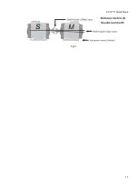
Misalignment of any rotating machine is expressed in parallel (Offset) and angular (Gap) of the shafts.
Most frequently in practice, both of them are present simultaneously. Different kinds of misalignment of
axes are shown in Fig. 2.
The parallel (Offset) and angular (Gap) misalignment of axes is determined in two mutually perpendicular
planes. For the purpose of elimination of the parallel and angular misalignment of axes, in each of the
planes a correction of position of the movable machine (M) will be done.
For the horizontal mounted machine – the movable machine (M) position is adjusted in the horizontal and
vertical planes.
For the vertical mounted machine, operator determines arrangement of the correction planes, basing on
considerations of the convenience and technological effectiveness of moving of the movable (M)
machine.
Stationary machine (S) - in the process of eliminating of the axes misalignment the position of this
machine stay static, i.e. it does not move.
Movable machine (M) – the machine, which position is adjusted for eliminating of the parallel and angular
misalignment of axes.
The measurement system calculates the values of the angular and parallel misalignment of axes in the
plane of the coupling (in two mutually perpendicular planes), and the adjustment values for the machine
feet on the movable (M) machine, that is necessary for elimination of this misalignment of axes. Fig. 3
shows misalignment of axes and the values for its correction just for vertical plane.
Parallel misalignment of axes – Offset (displacement)
Angular misalignment of axes – Gap
Parallel and angular misalignment of axes – ( Gap)
Fig 2


