AVV-711 Quick Book
14
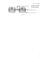
Fig 6.
S-M distance between measuring transducer units.
S-C distance between S and center of coupling.
S-F1 distance between stationary detector (S) and the feet pair 1 (F1).
S-F2 distance between S and F2 (must be longer than S-F1).
If the machine has three pairs
of feet, you can change this distance after finished measurement, and then repeat the
calculation
and get a new
adjustment
value for this pair.
Fig 7.
S-M distance between measuring transducer units.
S-C distance between S and center of coupling.
S-F1 distance between stationary detector (S) and the plane of alignment (F1).
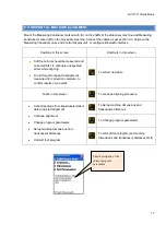
3.5 ROUGH ALIGNMENT PROCEDURE
Rough alignment should be applied only when the alignment is extremely poor, the laser beams may
travel outside the detectors during rotation of the shafts with the Measuring units mounted. If this happen
it is necessary to do a rough alignment first.
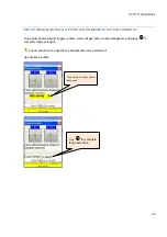
Rough alignment procedure (variant 1), (Fig. 8):
Turn shafts with measuring units to the 9 o’clock position. Aim the laser beams at the centre of the
closed detectors.
Turn shafts with measuring units to the 3 o’clock position.


