AVV-711 Quick Book
45
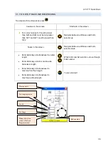
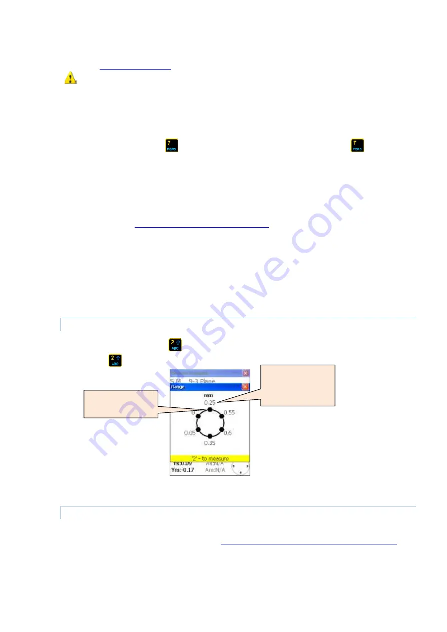
To eliminate angularity (gap) correct moveable machine central axis angle using shims with values
showed in
screen.
Do not change movable machine lateral position, while inserting/removing shims.
Single coordinate(Y) offset live alignment procedure
9-3 plane live alignment
To start 9-3 plane live alignment shafts should be in 9 or 3 o’clock position.
If you need to turn shaft press
to freeze. Turn shafts to desired position and press
to thaw. Do
not forget enter manual angle. After some averaging time desired plane should become enabled for live
update(blinking green checkbox appears at plane header) correction Loosen moveable machine feet and
start adjusting the movable machine position on 9-3 axis only.
6-12 plane live alignment
To start 6-12 plane live alignment shafts should be in 6 or 12 o’clock position.
Do shafts rotation as
described in 9-3 plane alignment section
. Plane 6-12 should become enabled for
live update. Loosen moveable machine feet and start adjusting the movable machine position on 6-12
axis only.
Biaxial (Y, X) offset live alignment procedure
Biaxial live alignment procedure mostly the same as the single coordinate procedure except that there no
need to turn shafts in to predefined positions and no need to turn shafts when change from horizontal to
vertical alignment and vise versa, but highly recommended turn shaft close to 45 evenly degree (45-135-
225-315) for equalize measurement errors.
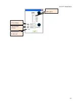
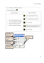
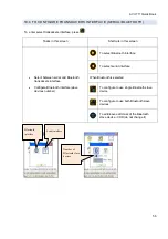
7.4.1 TO VIEW BOLTS CORRECTIONS
To view bolts corrections press
Bolts corrections values screen appears. To close bolts corrections
screen press
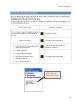
CONTINUE WORK AFTER THE TRANSDUCERS POSITION CHANGED
Before continue work after the transducers position changed it is necessary to take two initial position
measurement points. See horizontal alignment
continue work after the transducers position changed
for
details.
Bolt correction value
(shim thickness)
12 o’clock position

