AVV-711 Quick Book
84
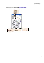
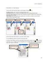
Fig. 14.4.1
1
2
3
4
5
3
4
5
6
Intended overlap positions 4 and 5
for the first piece and the 1 and 2
for the second one
First piece of straightness
position from no.1 to last point
no.5.
2
nd
piece of straightness position with from
point no.1 to no.6 but only no 1 and 2
selected as overlap position (re-measure
points).
2
1
T
Transmitter’s next position, for
second piece measurement


