AVV-711 Quick Book
12
3.0 MACHINE ALIG NMENT
·
Mount the Measuring transducer units on the shafts of the (S) and (M) machines
·
Select program according to the application of machine to be measured
·
Input the distances between the (S) and (M) units, the coupling and the movable machine
feet
·
Press
to record readings from the measuring units at three different positions of the
shafts
·
Adjust the machine feet position of the movable machine in accordance with correction
results of the calculated value on control screen
Attention!
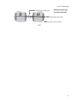
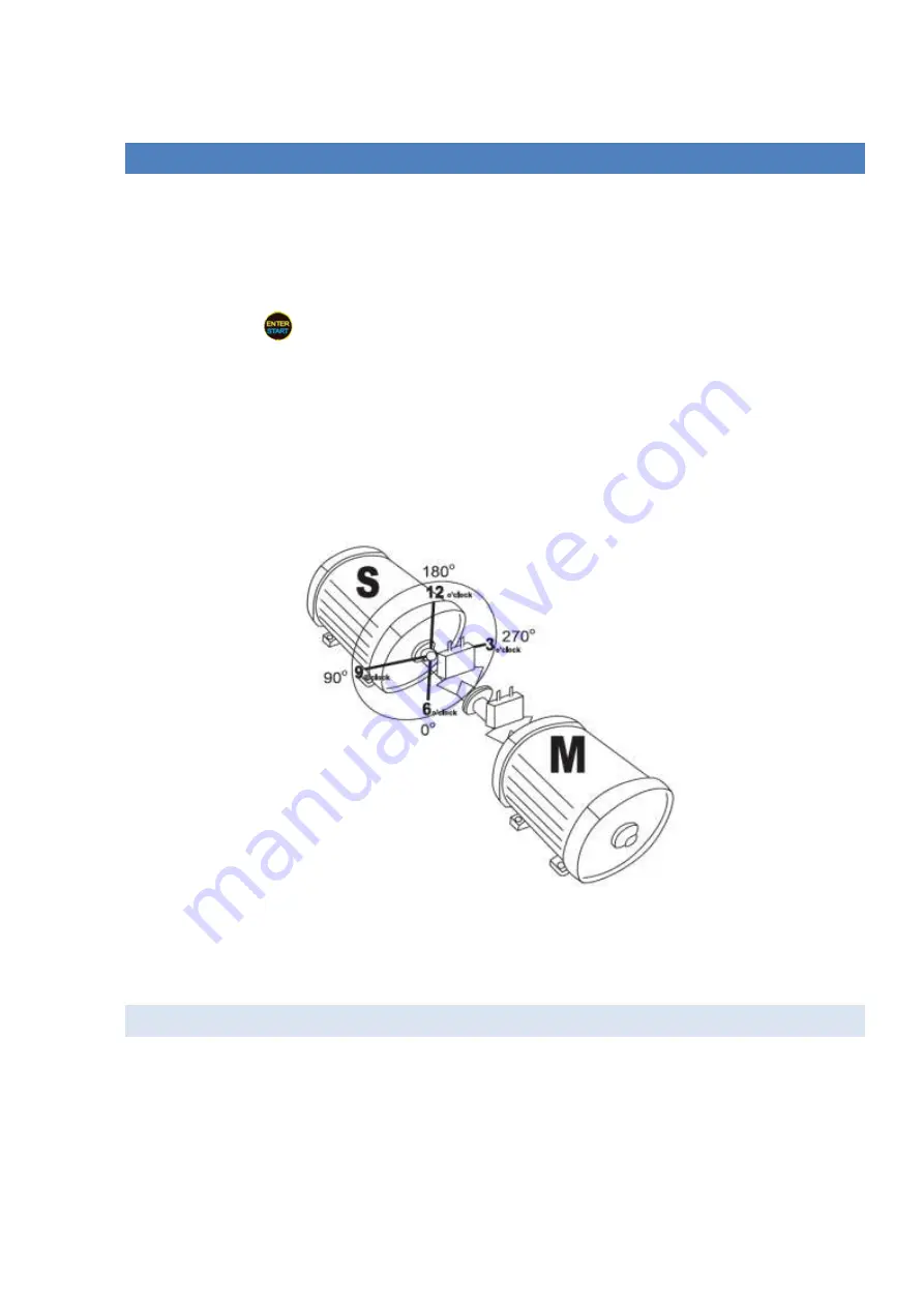
While making the measurement, it is necessary to observe and understand the orientation on rotation
direction of the shafts with the (S) and (M) measuring transducer units with regard to the relative position
of the (S) and (M) machines as in Fig.4.
Fig 4.
Fig. 4 shows the view of (S) machine from the (M) end view, at the 12:00 o’clock position. The measuring
transducer units have marking (S) and (M) on the top of each unit, should be mounted with brackets onto
the shafts of the (S) stationary and (M) movable machine respectively.
3.1 INPUT MEASURE MENT DATA
AVV-711 system function is based on the measurement of the laser beam movement on the detector
receiver’s window during the turning of shafts with the measuring units mounted.
To enable the System to carry out the shaft alignment calculation, it is necessary to record the
measurement data in minimum three positions of the shafts rotation. turning the shafts in the range of
180º is sufficient.


