AUTO PICLE-S
22
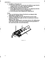
2 Installation of the guide rail.
a Secure the pipe to the cut and mark a line 450-mm away from the
cutting position. (4 locations along the periphery).
b Wind the guide rail along the marked line.
c Set the adjusting shaft (2) (see figure 4 - 3) in alignment with the
hole (while the hand clamp is being tightened)
d Secure the guide rail by tightening the adjusting nut.
Note:
•
Take care that the hand clamp (3) will not be unclamped while
tightening the adjusting nut (1).
•
Tighten the adjusting nut to the extent that the set hole in the
adjusting shaft (2) of the guide rail will not be deformed. (Tension:
Approx. 8 kg or less).
Tightening the adjusting nut is necessary only once for cutting pipes
of the same diameter. From the second time onward, operation of
the hand clamp alone will permit mounting.
figure 4 - 3
1
3
4
2
Auto Picle-S.book Page 22 Thursday, April 11, 2002 11:15 AM
Summary of Contents for AUTO PICLE-S
Page 1: ...AUTO PICLE S REMOTE CONTROL GAS MOTORIZED PIPE CUTTING MACHINE KOIKE SANSO KOGYO CO LTD...
Page 11: ...AUTO PICLE S 10...
Page 13: ...AUTO PICLE S 12...
Page 25: ...AUTO PICLE S 24...
Page 31: ...AUTO PICLE S 30...
Page 37: ...AUTO PICLE S 36...
Page 39: ...AUTO PICLE S 38 8 2 Assembly drawing figure 8 2...
Page 40: ...AUTO PICLE S 39 9 Parts list 9 1 Body unit...
Page 43: ...AUTO PICLE S 42 9 2 Driving unit...
Page 46: ...AUTO PICLE S 45 9 3 Electrical and gas unit...
Page 49: ...AUTO PICLE S 48 9 4 Guide rail...
Page 51: ...AUTO PICLE S 50...

