-9-
Fig. 3
The Model NR 3665DA mainly consists of two sections: the output section and the magazine section. The
most essential precautions on disassembly and reassembly of the Model NR 3665DA are described below.
1. Precautions on disassembly and reassembly
[Bold]
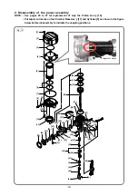
numbers in the description below correspond to the item numbers in the parts list and exploded
assembly diagram for the Model NR 3665DA.
WARNING: Be sure to remove the battery from the main body before starting repair or maintenance
work. If the switch is activated inadvertently with the battery still mounted on the main
body, the motor may turn unexpectedly and could cause serious injury.
1. Removal of the hook
Remove the Hook
[62]
by removing the Nylock Hex. Socket Hd. Bolts M4 x 8
[63]
for easy disassembly
work, although disassembly can be done without removing the Hook
[62]
.
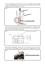
2. Removal of housing (C)
• When the nailer is enabled to nail, switch to the maintenance mode and move the Piston Ass'y
[16]
down to the bottom dead point referring to "Feeding compressed air" on page 29.
• Remove the Tapping Screw (W/Flange) D4 x 20
[47]
and remove Housing (C)
[48]
.
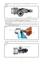
• Remove the Charge Cap
[8]
by using a hexagonal socket wrench.
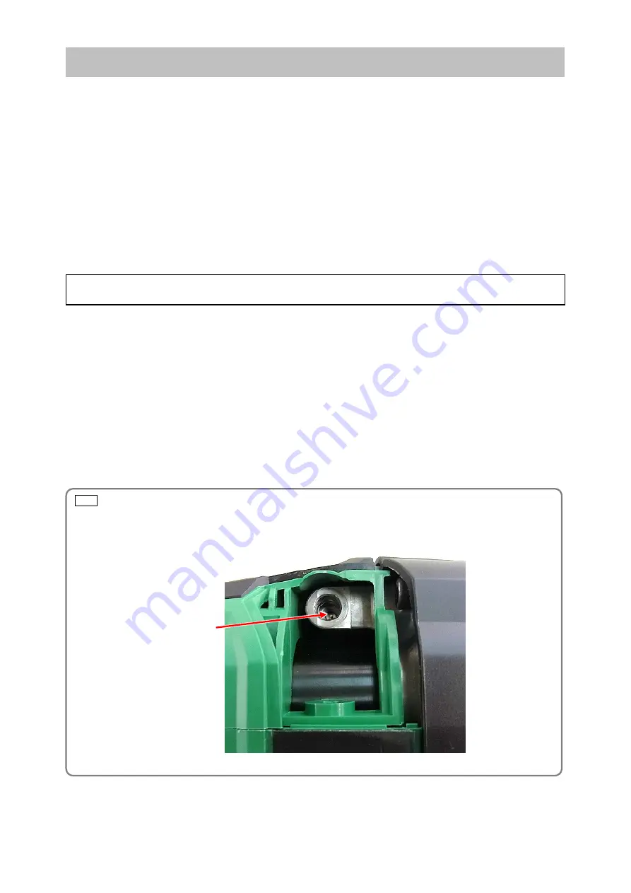
• Push the Valve Core
[10]
to release compressed air as shown below.
REPAIR GUIDE
Preparation before disassembly
[10]


