-18-
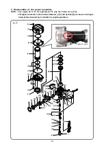
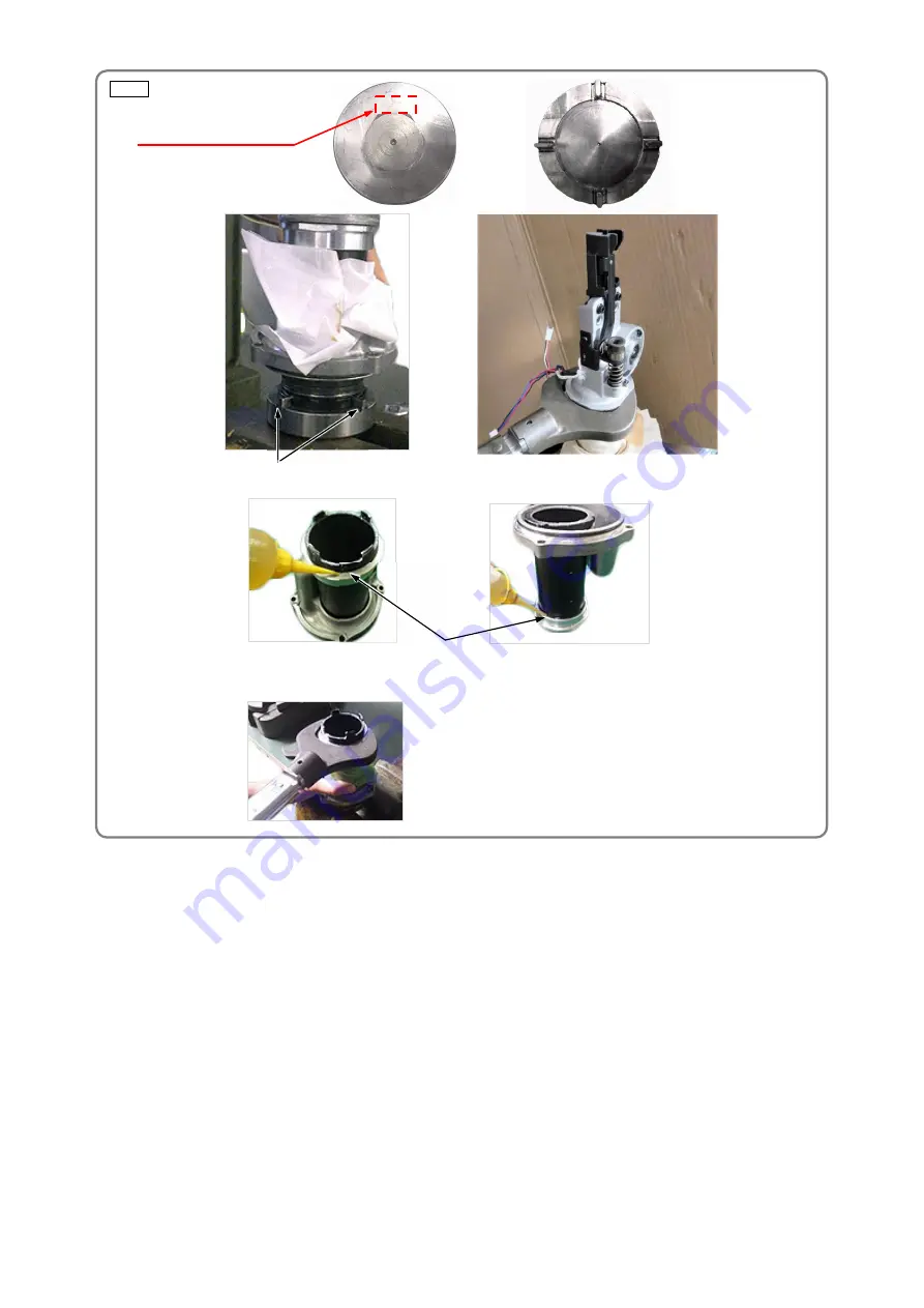
Fig. 20
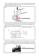
• Turn the Special Nut M58
[13]
and remove it from the Cylinder
[5]
.
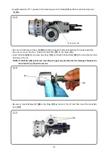
• Remove the Chamber Base Ass’y
[11]
from the Cylinder
[5]
being careful not to damage the sealing
surfaces.
• Remove the two O-rings (I.D 55.5)
[6]
from the Cylinder
[5]
.
• Remove the Slide Ring
[14]
and X-ring
[15]
from the Piston Ass'y
[16]
.
• Remove the Piston Bumper
[17]
from the Nose
[18]
.
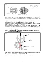
• Remove the Retaining Ring D52
[19]
from the Nose
[18]
and pull out the Bearing Holder
[20]
and Pin
Wheel
[28]
.
NOTE: The Pin Wheel [28] can be removed only after removing the Piston Ass'y [16].
• Remove the Ball Bearing 6000VV
[21]
and Ball Bearing 6902VV
[30]
from the Pin Wheel
[28]
.
• Remove the Needle Roller D3
[31]
from the Pin Wheel
[28]
and then remove the Position Detector
[23]
.
• Remove the eight Needle Rollers D4
[33]
and one Needle Roller D4.5
[24]
from the Pin Wheel
[28]
.
Remove Wheel Spring (A)
[32]
, Wheel Spring (B)
[29]
, and Pin (A)
[34]
.
• Remove Felt (P)
[25]
from the Pin Wheel
[28]
.
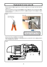
Fit the claws of the J-400 special socket in the
notches on the Cylinder
[5]
(4 places).
J-400
Repair tool number "J-400"
J-400 special socket (Code No. 372798)
• Apply 0.5 g or more oil to the top and bottom of the Special Nut M58
[13]
all around.
• Leave the Special Nut M58
[13]
as it is for at least 2 hours.
• Loosen the Special Nut M58
[13]
.
• If it is hard to loosen, apply additional oil to the Special Nut M58
[13]
and leave it for more than half a day. Then loosen it again.


