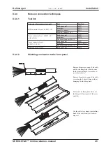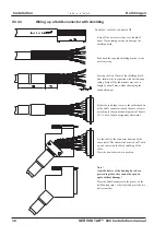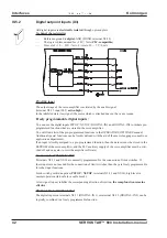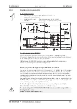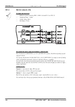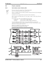
II.3.4.4
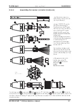
Assembling the resolver connector (motor end)
- A.4.029.4/6
SERVOSTAR™ 600 Installation-manual
31
Kollmorgen
02.99 - A.4.029.4/6
Installation
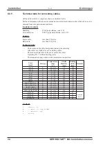
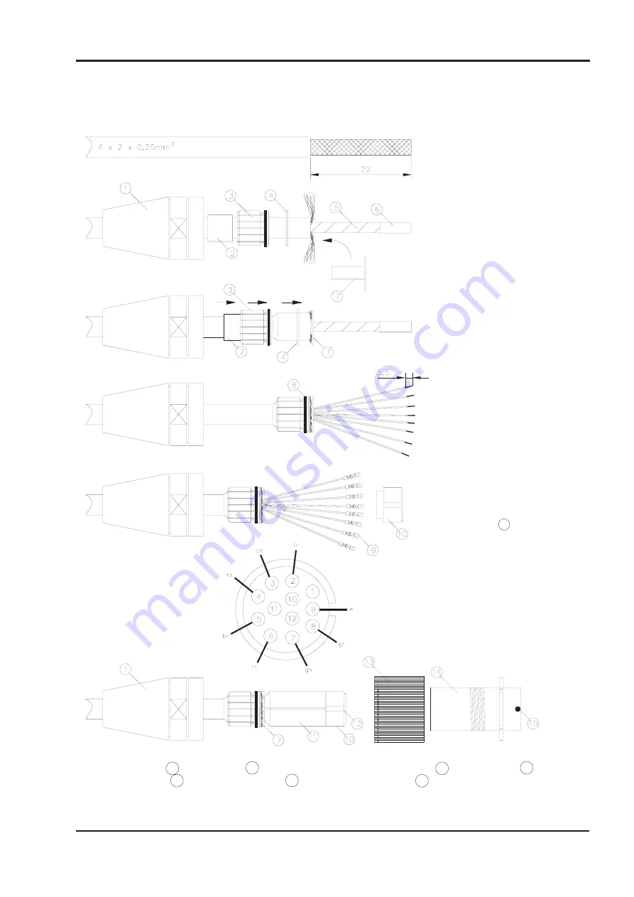
Strip off the outer covering over a
length of 22mm. Take care not to da-
mage the shielding braid.
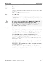
Push items
,
,
,
onto the
cable. Push up the shielding 90°.
Wrap the protective cloth
tightly
round the cores, and fix with adhesive
tape (e.g. Sellotape)
. Push the
shielding sleeve
onto the cable
(between the protective cloth and the
shielding braid).
Shorten the shielding braid all round,
do not let any shielding strands project
out of the shielding sleeve
.
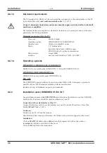
Push
and
up to the shielding
sleeve. Press the rubber ring
into
the strain relief
.
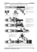
Make sure that no shielding strands
stick out. The O-ring
seals off the
contact area. Remove the adhesive tape,
protective cloth and filling cores. Strip
the cores.
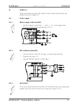
Use the appropriate crimp tool to
attach the crimp contacts
.
Push the crimp contacts into the
plastic insert
10
.
Caution !
Check the core colours .
Place the distance piece
11
between insert
10
and shielding sleeve
. Push the knurling
13
over insert sleeve
14
. Position the
insert in the insert sleeve
14
, so that the coding groove
12
is pushed over the coding stud
15
. Apply the special assembly spanner to the
insert sleeve, and screw the housing
tight up to the stop with an open-jaw spanner (22 a/f). Take care that the cable is not twisted
during this procedure.
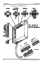
View :
inside of connector

