II.3.4.5
Wiring up the motor power connector (amplifier end)
- A.4.029.4/24
32
SERVOSTAR™ 600 Installation-manual
Installation
02.99 - A.4.029.4/24
Kollmorgen
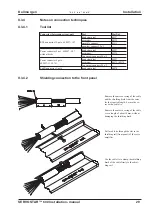
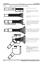
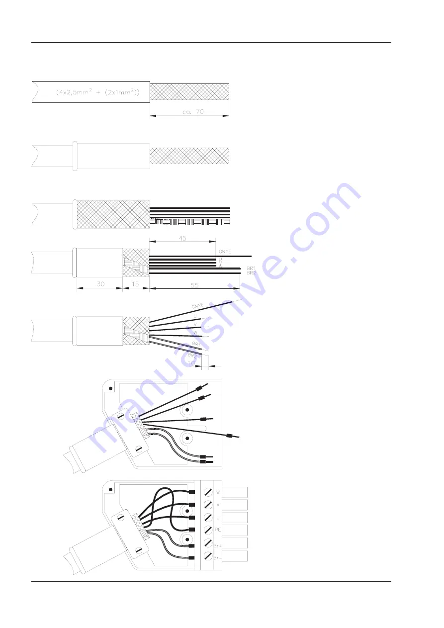
Strip off the outer covering over a length of
70mm, without damaging the shielding braid.
Push the grommet over the cable, until the
end is flush with the covering.
Push the outer shielding braid back over the
covering. Take out the shielding for the brake
cores and place it over the outer shielding
braid, in electrical contact. Push the filling
cores and protective cloth back over the
shielding.
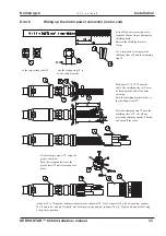
Push the shrink-wrap tubing (30mm long)
over the shielding, so that about 15mm
remain exposed. Use a hot-air blower to
shrink it.
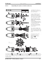
Shorten the cores U, V, W to 45mm, BR1,
BR2 to 55mm length.
Push the core ferrules into the corres- ponding
terminals in the connector. Follow the
connection diagram in
Chapter II.3.1.
Attach bootlace ferrules to the ends of the
cores.
Place the shielding plate in the connector
housing and push the contact tongues into the
PE terminal clamp of the connector and the
strain relief.
Fix the cable with the strain relief. Take care
that the clamping loop of the strain relief sits
properly on the shielding braid.
Strip off about 10mm of the ends of the cores,
without damaging the copper strands.

