III.5.2
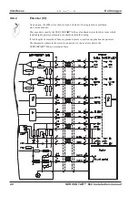
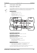
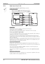
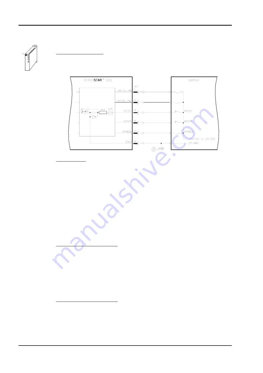
Digital setpoint inputs (X3)
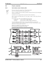
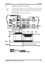
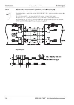
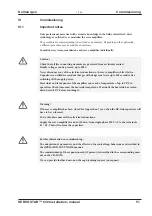
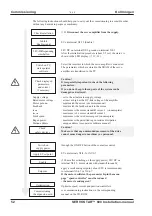
All digital inputs are electrically isolated through optocouplers.
Technical characteristics
—
Reference ground is digital-GND (DGND, terminal X3/18)
—
The logic is dimensioned for +24V / 7mA (PLC-compatible)
—
H-level of +12 — 30V / 7mA, L-level of 0 — 7V / 0 mA
ENABLE input
The output stage of the servo amplifier is activated by the enable signal
(terminal X3/15, input 24V, active-high).
In the inhibited state (low signal) the motor which is attached does not have any torque.
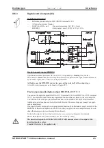
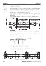
Freely programmable digital inputs :
You can use the digital inputs PSTOP / NSTOP / DIGITAL-IN1 and DIGITAL-IN2 to initiate pre-
programmed functions that are stored in the servo amplifier.
You will find a list of the pre-programmed functions in the OPERATOR SOFTWARE manual.
Additional special functions can be freshly defined with the aid of the macro language (consult our
applications department).
If an input is freshly assigned to a pre-programmed function, then the data set must be stored in the
EEPROM of the servo amplifier, and the 24V auxiliary supply of the servo amplifier must be swit-
ched off and on again (to reset the amplifier software).
Limit-switches PSTOP / NSTOP
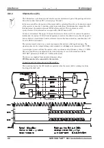
Terminals X3/13 and X3/14 are normally programmed for the connection of limit switches. If
these inputs are not needed for the connection of limit switches, then they are freely programmable
for other input functions.
Limit-switch positive/negative (PSTOP / NSTOP, terminals X3/13 and X3/14), high level in
normal operation (fail-safe for a cable break).
A low signal (open) inhibits the corresponding direction of rotation, the ramp function remains
effective.
DIGITAL-IN 1 / DIGITAL-IN 2
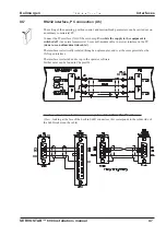
The digital inputs on terminals X3/11 (DIGITAL-IN 1) or terminal X3/12 (DIGITAL-IN 2) can be
logically combined in a freely programmable function.
- A.4.031.1/24
42
SERVOSTAR™ 600 Installation-manual
Interfaces
02.99 - A.4.031.1/24
Kollmorgen

