III.5.3
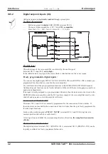
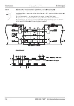
Digital control outputs (X3)
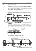
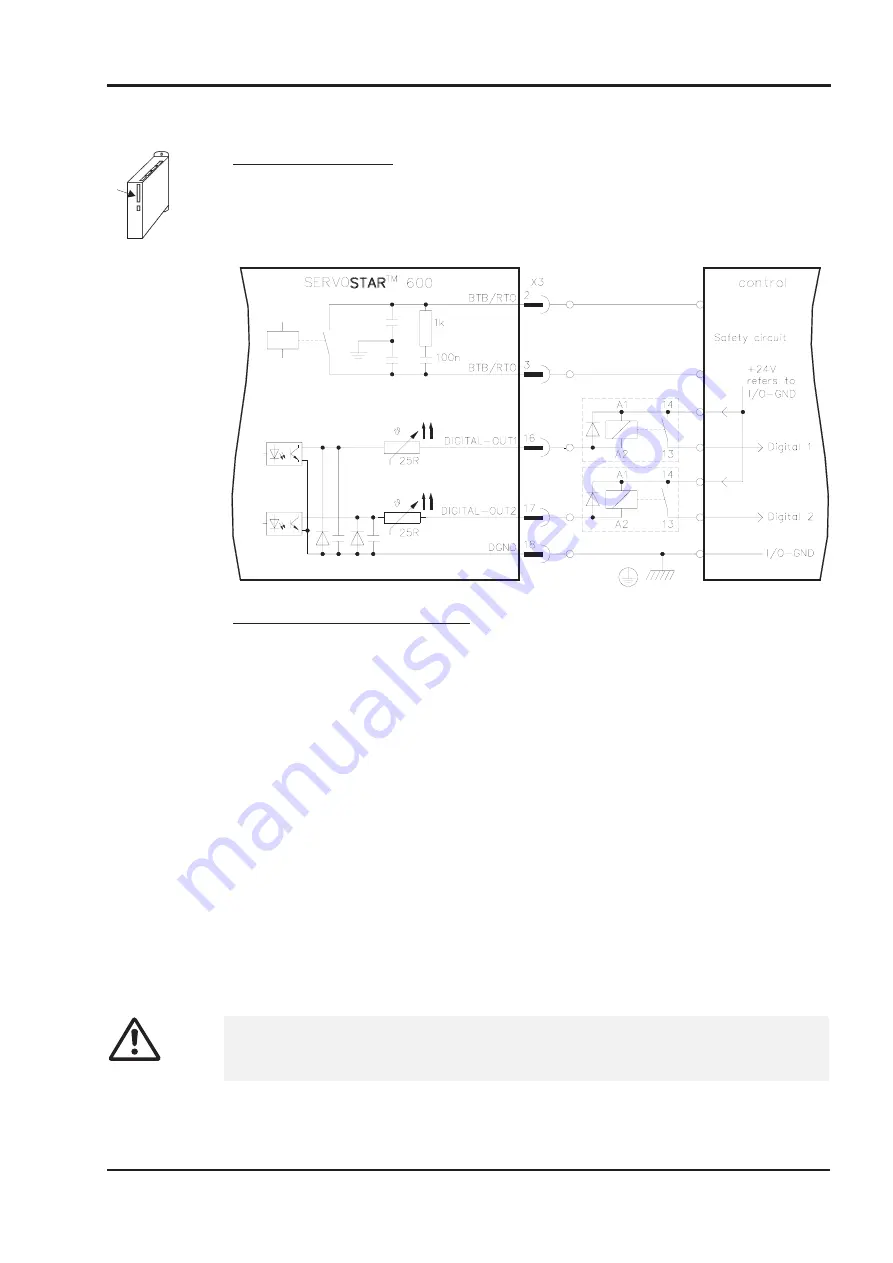
Technical characteristics
—
Reference ground is digital-GND (DGND, terminal X3/18)
—
All digital outputs are floating
—
DIGITAL-OUT1 and 2
: Open-collector, max. 24V DC, 10 mA
BTB/RTO
: Relay output, max. 24V DC, 42V AC, 0.5A
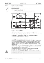
Ready-to-operate contact BTB/RTO
Operational readiness (terminals X3/2 and X3/3 ) is signalled by a floating relay contact.
The contact is closed when the servo amplifier is ready for operation, the signal is not influenced
by the enable signal, the I²t- limit, or the regen threshold.
All faults cause the BTB/RTO contact to open and the switch-off of the output stage.
A list of the error messages can be found in Chapter IV.3.
Freely programmable digital outputs DIGITAL-OUT 1 / 2
:
You can use the digital outputs DIGITAL-OUT1 (terminal X3/16) and DIGITAL-OUT2 (terminal
X3/17) to outputs messages from pre-programmed functions that are stored in the servo amplifier.
You will find a list of the pre-programmed functions in the OPERATOR SOFTWARE manual.
Additional special functions can be defined with the aid of the macro language (consult our appli-
cations department).
If an input is freshly assigned to a pre-programmed function, then the data set must be stored in the
EEPROM of the servo amplifier, and the 24V auxiliary supply of the servo amplifier must be swit-
ched off and on again (to reset the amplifier software).
Evaluate the outputs via inverting interface relays (see connection diagram), for example
Phönix DEK-REL-24/I/1 (turn-on delay 6 ms, turn-off delay 16ms).
The described logic in the OPERATOR SOFTWARE manual refers to the output of the
inverting interface relays.
Consider the delay of the applied relay !
- A.4.031.1/20
SERVOSTAR™ 600 Installation-manual
43
Kollmorgen
02.99 - A.4.031.1/20
Interfaces

