VI.4
Index
SERVOSTAR™ 600 Installation-manual
67
Kollmorgen
02.99
Appendix
!
24V supply
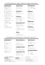
20A . . . . . . . . . . . . . . . . . . . . 58
5A . . . . . . . . . . . . . . . . . . . . . 57
24Vaux. supply, interface . . . . . . . . . . . 37
A
abbreviations . . . . . . . . . . . . . . . . . . 8
AGND . . . . . . . . . . . . . . . . . . . . . 17
ambient temperature. . . . . . . . . . . . . . 16
assembly. . . . . . . . . . . . . . . . . . . . 22
B
Baudrate . . . . . . . . . . . . . . . . . . . . 53
brake. . . . . . . . . . . . . . . . . . . . . . 17
BTB/RTO . . . . . . . . . . . . . . . . . . . 43
C
CANopen-Interface . . . . . . . . . . . . . . 48
CE-conformance . . . . . . . . . . . . . . . . 7
Commissioning . . . . . . . . . . . . . . . . 51
conductor cross-sections . . . . . . . . . . . 16
connection diagram . . . . . . . . . . . . . . 26
connection techniques . . . . . . . . . . . . . 29
Contents . . . . . . . . . . . . . . . . . . . . 3
D
DC-link interface . . . . . . . . . . . . . . . 37
DGND . . . . . . . . . . . . . . . . . . . . . 17
disposal . . . . . . . . . . . . . . . . . . . . 61
E
EMC . . . . . . . . . . . . . . . . . . . . . . 21
Emergency Stop strategies . . . . . . . . . . 20
encoder
emulations. . . . . . . . . . . . . . . . . 45
interface . . . . . . . . . . . . . . . . . . 40
interface master-slave . . . . . . . . . . . 50
error messages. . . . . . . . . . . . . . . . . 56
external fusing. . . . . . . . . . . . . . . . . 15
F
forming . . . . . . . . . . . . . . . . . . . . 51
G
Glossary . . . . . . . . . . . . . . . . . . . . 64
ground symbol . . . . . . . . . . . . . . . . 24
grounding
connection diagram . . . . . . . . . . . . 26
installation. . . . . . . . . . . . . . . . . 25
H
hardware requirements . . . . . . . . . . . . 36
holding brake . . . . . . . . . . . . . . . . . 17
humidity . . . . . . . . . . . . . . . . . . . . 61
I
inputs
analog setpoints . . . . . . . . . . . . . . 41
DIGI-IN 1/2 . . . . . . . . . . . . . . . . 42
enable . . . . . . . . . . . . . . . . . . . 42
NSTOP . . . . . . . . . . . . . . . . . . 42
PSTOP . . . . . . . . . . . . . . . . . . 42
installation
hardware . . . . . . . . . . . . . . . . . 24
software . . . . . . . . . . . . . . . . . . 36
K
key operation . . . . . . . . . . . . . . . . . 54
L
LC-Display . . . . . . . . . . . . . . . . . . 54
LED display . . . . . . . . . . . . . . . . . . 16
Limit Switch Inputs . . . . . . . . . . . . . . 42
M
mains supply connection, interface . . . . . . 37
maintenance . . . . . . . . . . . . . . . . . . 61
master-slave . . . . . . . . . . . . . . . . . . 50
monitor outputs . . . . . . . . . . . . . . . . 44
motor
interface . . . . . . . . . . . . . . . . . . 38
motor cable . . . . . . . . . . . . . . . . 34
motor choke
connection example . . . . . . . . . . . . 27
motor holding brake . . . . . . . . . . . . . . 17
mounting position . . . . . . . . . . . . . . . 16
multi-axis systems
connection example . . . . . . . . . . . . 27
N
nameplate . . . . . . . . . . . . . . . . . . . 10
NSTOP . . . . . . . . . . . . . . . . . . . . 42
O
options. . . . . . . . . . . . . . . . . . . . . 11
other operating systems . . . . . . . . . . . . 36
outputs
BTB/RTO . . . . . . . . . . . . . . . . . 43
DIGI-OUT 1/2 . . . . . . . . . . . . . . 43
Monitor1/2 . . . . . . . . . . . . . . . . 44
P
Package supplied . . . . . . . . . . . . . . . 10
Parameter setting . . . . . . . . . . . . . . . 53
PC cable . . . . . . . . . . . . . . . . . . . . 47
PC connection . . . . . . . . . . . . . . . . . 47
PGND . . . . . . . . . . . . . . . . . . . . . 17
pin assignments . . . . . . . . . . . . . . . . 28
pollution level . . . . . . . . . . . . . . . . . 16
protection . . . . . . . . . . . . . . . . . . . 16
PSTOP. . . . . . . . . . . . . . . . . . . . . 42
pulse-direction, interface . . . . . . . . . . . 49
R
Regen circuit . . . . . . . . . . . . . . . . . 18
resolver
cable. . . . . . . . . . . . . . . . . . . . 34
interface . . . . . . . . . . . . . . . . . . 39
ROD interface . . . . . . . . . . . . . . . . . 45
RS232/PC, interface. . . . . . . . . . . . . . 47
S
safety instructions . . . . . . . . . . . . . . . 6
setpoint inputs . . . . . . . . . . . . . . . . . 41
SETUP.EXE. . . . . . . . . . . . . . . . . . 36
shielding
connection diagram . . . . . . . . . . . . 26
installation. . . . . . . . . . . . . . . . . 25
site . . . . . . . . . . . . . . . . . . . . . . . 25
site altitude . . . . . . . . . . . . . . . . . . 16
SSI, interface . . . . . . . . . . . . . . . . . 46
stacking height . . . . . . . . . . . . . . . . 61
standards . . . . . . . . . . . . . . . . . . . . 7
storage . . . . . . . . . . . . . . . . . . . . . 61
storage duration . . . . . . . . . . . . . . . . 61
storage temperature . . . . . . . . . . . . . . 61
supply voltage . . . . . . . . . . . . . . . . . 16
Switch-on and switch-off behaviour . . . . . 19
system components, overview . . . . . . . . 14
T
technical data . . . . . . . . . . . . . . . . . 15
trailing cables . . . . . . . . . . . . . . . . . 34
transport . . . . . . . . . . . . . . . . . . . . 61
U
use as directed . . . . . . . . . . . . . . . . . 9
operator software . . . . . . . . . . . . . 35
servo amplifier . . . . . . . . . . . . . . . 9
V
ventilation
Installation . . . . . . . . . . . . . . . . 25
Tech.Data . . . . . . . . . . . . . . . . . 16
W
Warning messages . . . . . . . . . . . . . . 56
wiring . . . . . . . . . . . . . . . . . . . . . 25
X
XGND . . . . . . . . . . . . . . . . . . . . . 17
Text
Seite
Text
Seite

