III.6.2
SSI-Interface (X5)
The SSI interface (synchronous serial absolut-encoder emulation) is part of the package delivered.
Select the encoder function SSI (screeen page “Encoder”).
In the servo amplifier, the position of the motor shaft is calculated from the cyclic-absolute signals
of the resolver or encoder. A position output is generated from this information, compatible with
the data format of normal commercial SSI absolute encoders. This synchronous, serial,
cyclic-absolute 12-bit information is output on the SubD-Connector X5.
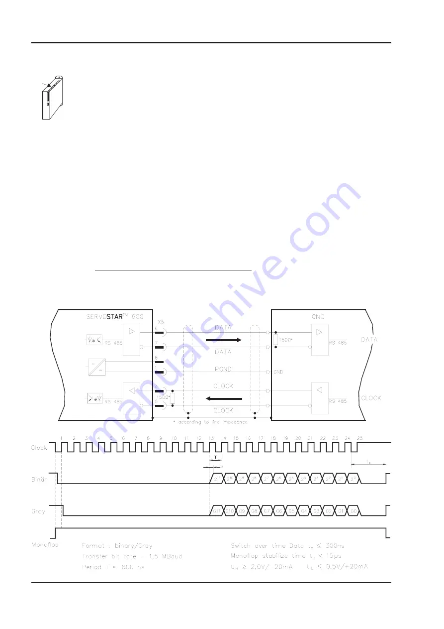
24 bits are transmitted. The upper 12 bits are fixed at zero, the lower 12 bits contain the position
information. Exception : If a SinCoder (Stegmann) is used as a feedback device, then the upper 12
bits are held at 1 (invalid data !) until a reference traverse has been carried out, and then they will
be set to ZERO (valid data !).
The interface must be read in as a multi-turn encoder, but delivers valid single-turn data. The
signal sequence can be output in Gray code (standard) or in binary code (parameter SSI-CODE).
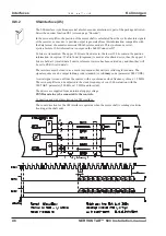
A serial signal is read out from the control, with a synchronous clock frequency of max. 1.5 MHz.
The servo amplifier can be adjusted to the clock frequency of your SSI-evaluation with the
SSI-TAKT parameter (200 kHz or 1.5MHz and inverted).
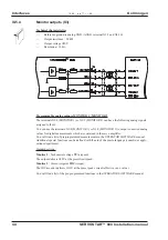
The drivers are supplied from an internal supply voltage.
PGND must always be connected to the controls.
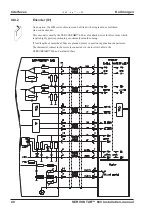
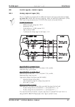
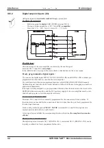
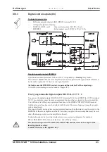
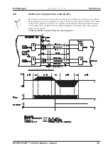
Connection and signal description for SSI interface :
The count direction for the SSI interface is upwards when the motor shaft is rotating clockwise
(looking at the shaft end).
- A.4.031.1/12
46
SERVOSTAR™ 600 Installation-manual
Interfaces
02.99 - A.4.031.1/12
Kollmorgen


