10.2 Verification
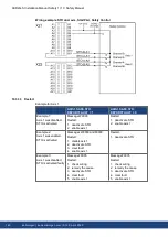
Check and verify the STO wiring (examples (
# 139)). The installation must be verified by
trained personnel after any changes to the installation. The expertise of the personnel must
be appropriate to the complexity and safety integrity level of the drive system.
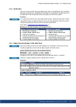
Proof test
You must test the STO function after initial start of the axis, after each intervention into the
wiring of the system, or after exchange of one or several components of the drive system.
The proof test intervall shall be one year to meet the required PFH.
Precondition:
= 1
Warning:
Do not enter hazardous area during proof test!
Method 1, axis remain enabled
Method 2, axis disabled
1. Stop the axis to standstill.
2. Caution: Block vertical load.
3. Keep the axis enabled.
4. Activate the STO function for example by
opening the protective screen.
5. The axis displays fault F9000.
1. Stop the axis to standstill.
2. Caution: Block vertical load.
3. Disable the axis.
4. Activate the STO function, for example,
by opening the protective screen
5. The axis displays fault W9000.
10.3 Safety Function Option 1 (I/O, SIL2 PLd)
Beta drives: Safety functions are neither approved nor certified yet. Do not use this func-
tionality in applications with functional safety request until further notice.
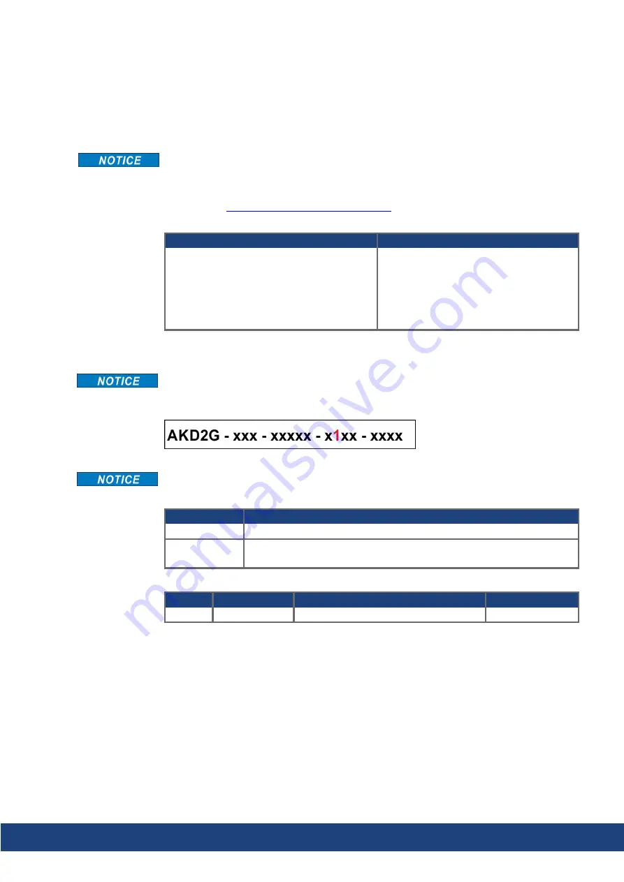
Valid for AKD2G devices with Functional Safety Option 1:
The safety function STO on the AKD2G with functional safety option 1 is certified.
The drive is ready to operate with pre-configured STO function.
Standards
Standard
Content
ISO 13849:2015 Safety of machinery: Safety-related parts of control systems
IEC 62061:2015 Functional safety of electrical/electronic/programmable electronic safety-
related systems
Available Safety Functions
Abbr.
Function
Activation
Refer to
STO
Safe Torque Off Safe digital inputs for one or for both axis
AKD2G-S Installation Manual, Safety 1 | 10 Safety Manual
Kollmorgen | kdn.kollmorgen.com | S102, April 2020
137

