6.6 Electrical Motor Braking
6.6.1 Drive Dynamic Braking
Drive Dynamic braking is a method to slow down a servo system by dissipating the mech-
anical energy driven by the motor back EMF.
Drive dynamic braking is not functional safe.
The AKD2G has a built in advanced drive dynamic braking mode which operates fully in hard-
ware. When activated, the drive powers the motor terminals with voltages to maximize the
stopping force per amount of motor current. This advanced method forces all of the dynamic
braking current to be stopping current and insures the fastest stopping per ampere of motor
terminal current.
When current is not being limited, the mechanical energy is being dissipated in the motor
winding resistance.
When current is being limited, energy is returned to the drive bus capacitors.
The drive also limits the maximum dynamic braking motor terminal current by using the
AXIS#.DBILIMIT
parameter to insure that the drive, motor, and customer load do not see
excessive currents/forces.
Whether and how the AKD2G uses dynamic drive braking depends on (
AXIS#.DISMODE
).
6.6.2 Regeneration breaking
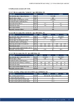
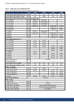
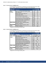
When the amount of returned energy from the motor builds the bus capacitor voltage up
enough the drive activates the regenerative braking circuit to start dumping the returned
energy in the regen resistor (also called regenerative resistor or brake resistor). All AKD2G
offer internal resistor plus the ability to connect an external resistor depending on the applic-
ation requirements.
External regen resistors are described in the regional
Accessories Manual
.
6.6.2.1 Functional description
1. Individual drives, not coupled through the DC bus link circuit (+DC, -DC)
When the energy fed back from the motor has an average or peak power that exceeds the pre-
set level for the brake power rating, the drive generates the warning "W2010 Regen Energy
Critical”. If the power exceeds the set fault level, the regenerative circuit will switch off and
the drive will disable.
2. Several drives coupled through the DC bus link (+DC, -DC)
Using the built-in regenerative circuit, several drives of the same series can be operated from
a common DC-bus link (
# 76), without any additional measures. 90% of the combined
power of all the coupled drives is always available for peak and continuous power. If the
power of the drive with the lowest switch-off threshold (resulting from tolerances) exceeds
the set fault level, the regenerative circuit will switch off on that drive.
Switch-off on over voltage
: With the regenerative circuit switched off, the returned energy
is not dissipated and therefore the DC-bus link level increases. The drive reports an over-
voltage fault if the DC-bus voltage threshold is exceeded. When this happens, the drive
power stage is immediately disabled and the load coasts to a stop with the fault message
“F2006 Bus Over voltage".
The ready to operate contact (terminals X21/B5-B6) is opened (
Observe the regeneration time (some minutes) after full load with peak brake power.
AKD2G-S Installation Manual, Safety 1 | 6 Technical description and data
Kollmorgen | kdn.kollmorgen.com | July 2020
37

