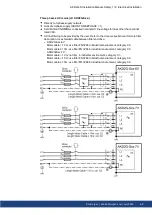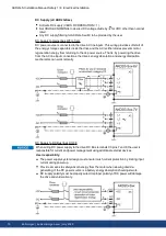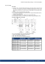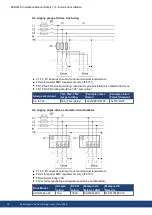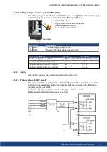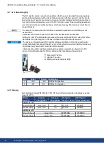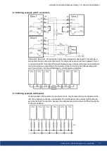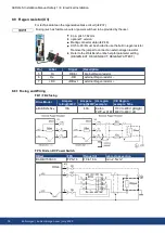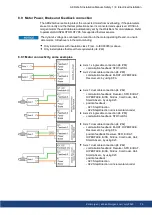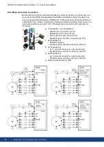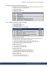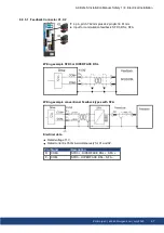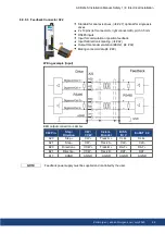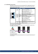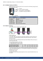
8.9.3.1 Motor power and motor brake connectors X1, X2
Usually these lines are part of the Kollmorgen motor cable connected to X1 or X2. For motor
brake safety notes and functional details (
Use Kollmorgen cables
Mating connector data (
Cable length: (
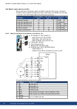
Pin Signal
Description
1
U
Motor phase U
2
V
Motor phase V
3
W
Motor phase W
5
PE
Protective earth
B+
BR+
Brake positive, with Kollmorgen cables only
B-
BR-
Brake negative, with Kollmorgen cables only
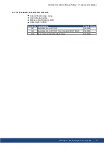
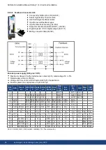
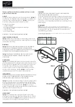
8.9.3.2 Feedback connectors X1, X2, X41, X21, X22, X23
Use Kollmorgen cables
Mating connector data (
Cable length: (
For feedback connection overview (
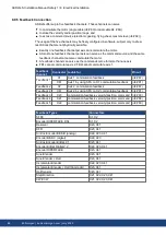
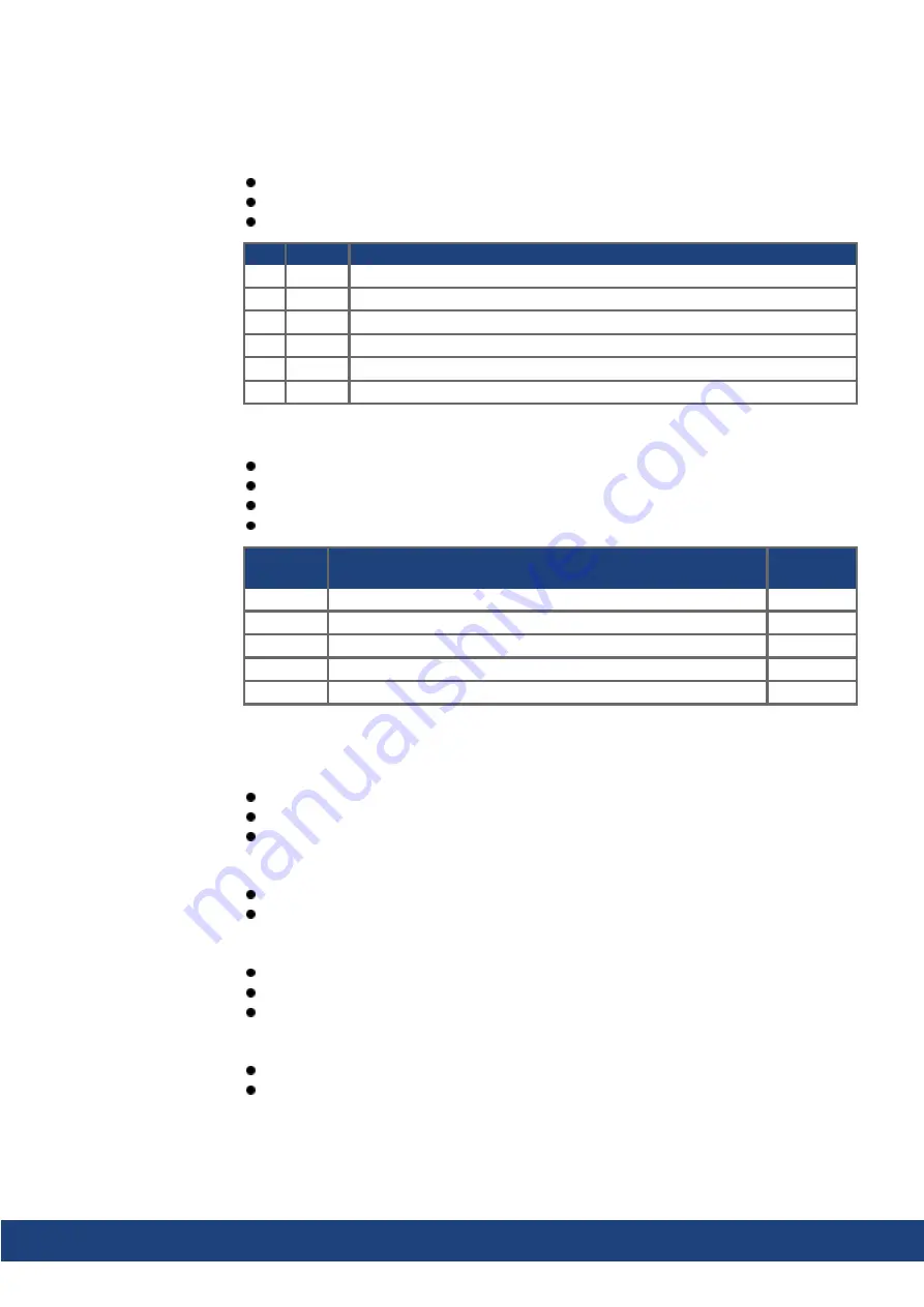
Connector Functionality
Pinout,
Wiring
X1/X2
SFD3, DSL, SFA
X41
SFA at X1 or X2 , several conventional feedback types
X21
Step/Direction, CW/CCW
X22
Step/Direction, CW/CCW, Incr. Encoder, EnDAT, BiSS
X23
Several conventional feedback types
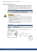
Feedback connector X1, X2, X41
Conventional feedback systems can be connected to X1 or X2 by using the optional feed-
back adapter SFA. SFA offers the additional connector X41.
Connector X1 is a standard connector. Input for SFD3, DSL, or SFA.
Connector X2 is standard for dual-axis drives. Input for SFD3, DSL, or SFA.
SFA: adapter for several conventional feedback types
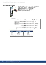
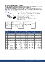
Feedback connector X21
Connector X21 is a standard connector.
Input for Step/Direction and CW/CCW.
Feedback connector X22
Connector X22 is standard connector for dual-axis drives.
Connector X22 is part of option DX or IO for single axis drives.
Input for Step/Direction, CW/CCW, Incremental encoder
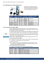
Feedback connector X23
Connector X23 is part of option DX or F3.
Input for several conventional feedback types.
AKD2G-S Installation Manual, Safety 1 | 8 Electrical Installation
Kollmorgen | kdn.kollmorgen.com | July 2020
83

