8.11 EtherNet Fieldbus Interface (X11/X12)
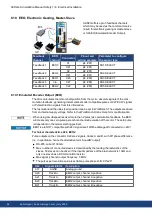
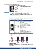
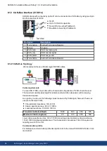
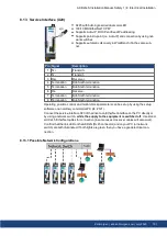
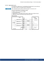
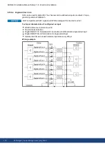
The EtherNet Fieldbus interface has two RJ-45 connectors.
RJ-45 with built-in green/red dual-color LED.
EtherCAT®
EtherNet/IP*
PROFINET*
* available 2021
Do not connect the Service line for the PC with the set up software to the EtherNet Fieldbus
interface X11/X12. The service EtherNet cable must be connected to X20.
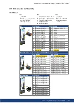
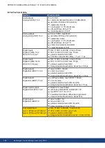
EtherNet Fieldbus interface X11/X12 pinout depends on the used protocol. Refer to the
matching fieldbus communication manual.
8.11.1 EtherCAT®
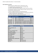
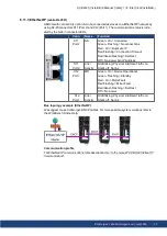
AKD2G drives (connectivity option
E
) can be connected as slaves to the EtherCAT® net-
work (CoE) by using RJ-45 connectors X11 (out port) and X12 (in port). The communication
status is indicated by the built-in connector LEDs.
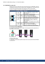
Conn.
Name
Function
X11 „Out“ „ERR“
Returns potentials communication failures:
Off = No Error
Blinking = Invalid configuration
Single Flash = Local error
Double Flash = Process data watchdog
X11 „Out” Link/
Activity
On/Blinking: Physical link/Data Traffic on.
Static off: No link.
X12 „In“
„RUN“
Returns the device state:
Off = INIT
Blinking = PRE-OPERATIONAL
Single Flash = SAFE-OPERATIONAL
On = OPERATIONAL
Flickering = Initialization or BOOTSTRAP
X12 „In”
Link/
Activity
On/Blinking: Physical link/Data Traffic on.
Static off: No link.
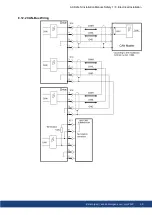
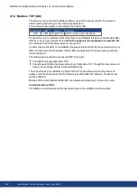
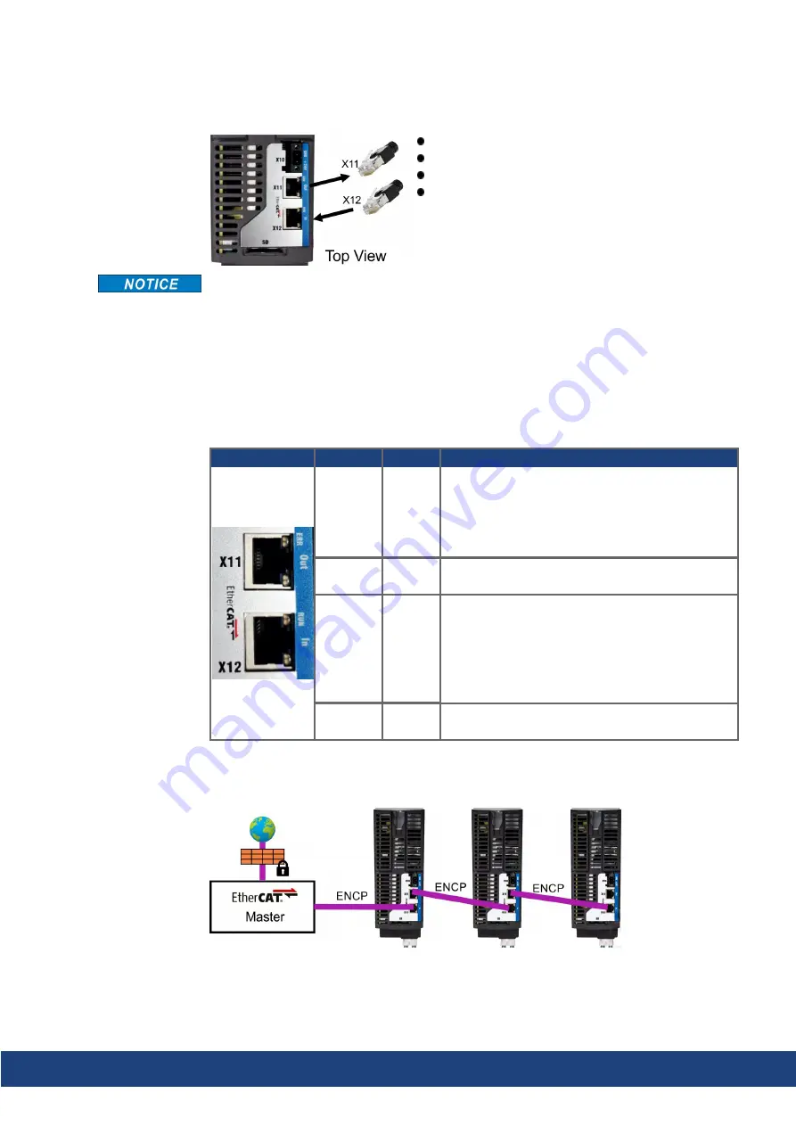
Bus topology example (EtherCAT®)
We suggest to use Kollmorgen ENCP cables. For more possible system solutions refer to
the WorkBench Online Help.
Communication profile
For EtherCAT® communication profile description refer to the manual "
AKD2G EtherCAT®
Communication
".
AKD2G-S Installation Manual, Safety 1 | 8 Electrical Installation
Kollmorgen | kdn.kollmorgen.com | July 2020
95

