6.7 LCD Display and Push-buttons (B1, B2)
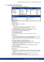
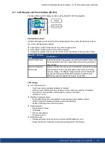
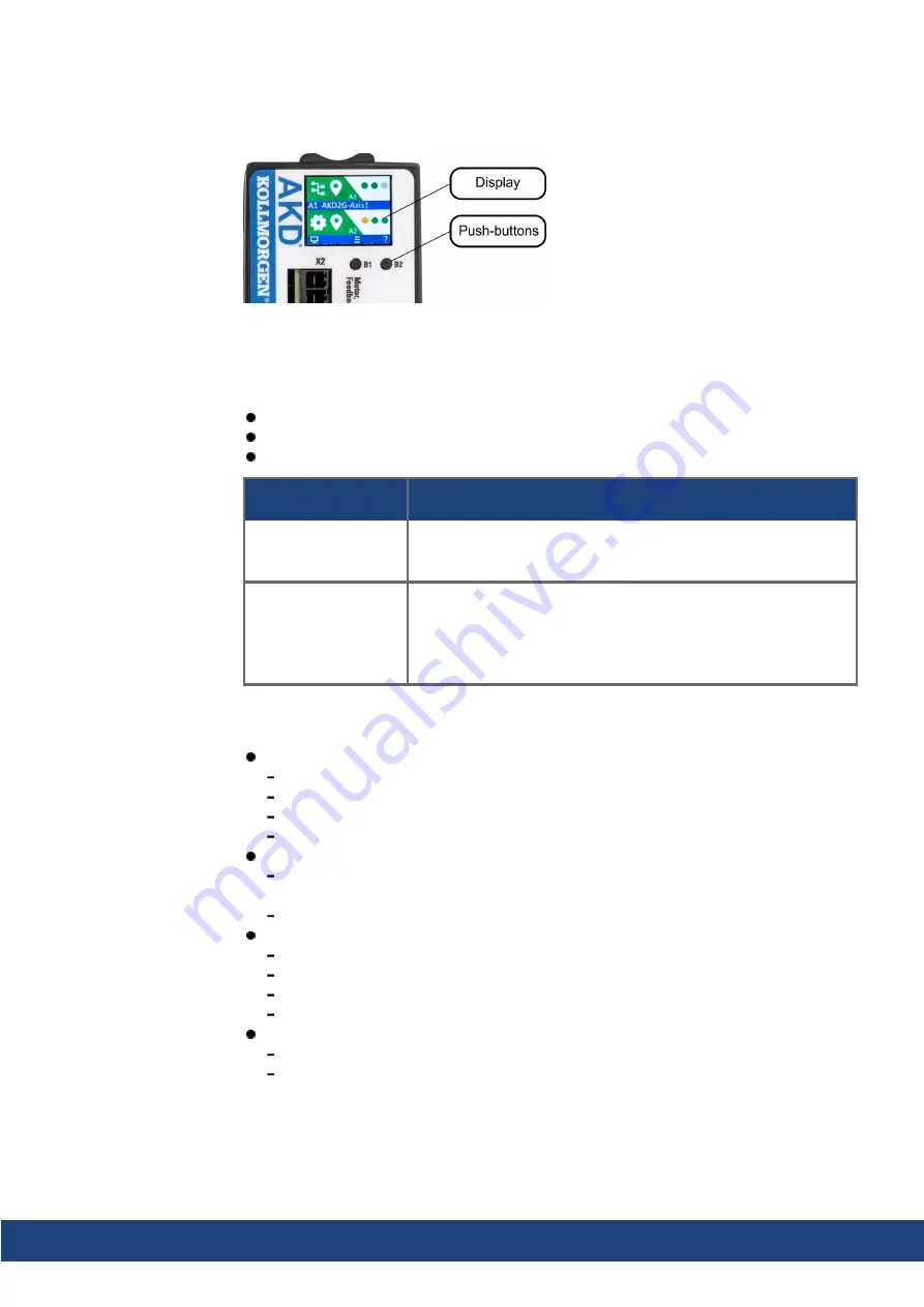
The drive offers an LCD display and two push-buttons B1 / B2 for navigation.
Push-button actions
A short button press invokes the action corresponding to the symbol directly above the but-
ton. On the dashboard for example,
a short press on B1 causes the menu system to appear, and
a short press on B2 causes a help screen to appear.
A long press (greater than 2 seconds) on B2 returns the display to the previous screen.
More B1 / B2 Func-
tions
Description
Boot from SD card
Push both buttons during power up to boot with data from SD card.
Press the buttons first, then hold it down while turning on the 24 V
power supply.
Boot from flash fall-
back image
Remove the SD card, then press both buttons and hold them down
while turning on the 24 V power supply to boot from an on-board
recovery image. The fallback image includes a set of bootloader,
operational, and control FPGA that implements sufficient pro-
gramming support to update missing or corrupt files.
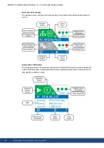
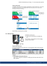
LCD display
Left Colored section
Color: axis status (enabled, disabled, or faulted).
First icon: axis command source (analog, service, electronic gearing, or fieldbus).
Second icon: axis operation mode (torque, velocity, or position).
Axis ID: A1 or A2.
Right Non-colored section:
No Fault/Warning: three virtual LEDs corresponding to axis disable sources
(Safe Torque Off, Hardware Enable, and Controlled Stop).
Faults or warnings: fault or warning code.
Center blue bar:
Drive and axis names
IP address
Drive model number
Firmware version
Bottom blue bar:
indicates whether the service port is connected to WorkBench, and
shows the actions that will be invoked by pushing the B1 / B2 buttons.
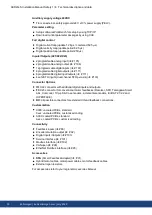
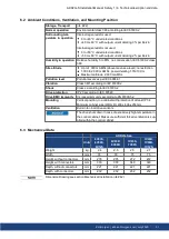
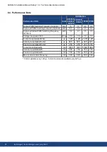
AKD2G-S Installation Manual, Safety 1 | 6 Technical description and data
Kollmorgen | kdn.kollmorgen.com | July 2020
39

