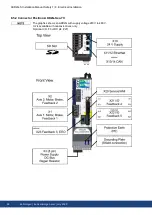
8.2 Guide to electrical installation
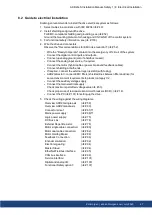
Kollmorgen recommends to install the drive electrical system as follows:
1. Select cables in accordance with IEC 60204 (
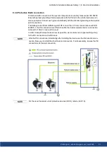
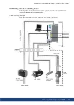
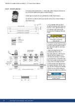
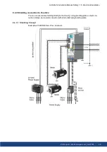
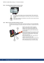
2. Install shielding and ground the drive.
For EMC-compliant shielding and grounding, see (
Ground the mounting plate, motor housing and CNC-GND of the control system.
3. For functional safety information, see (
4. Wire the drive and connectors.
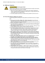
Observe the "Recommendations for EMI noise reduction": (
Wire the "Ready to Operate" contact into the emergency off circuit of the system.
Connect the digital control inputs and outputs.
Connect up analog ground (also if a fieldbus is used).
Connect the analog input source, if required.
Connect the motor (hybrid cable or power, brake and feedback cables).
Connect shielding at both ends.
If required, connect the external regen resistor (with fusing).
AKD2G-Sxx-6V: connect EMC filters (shielded lines between filter and drive) for
second environment requirements to product category C2.
Connect the auxiliary voltage supply
Connect the main electrical supply.
Check maximum permitted voltage value (
Check proper use of residual-current circuit breakers (RCD): (
Connect the PC (
# 101) for setting up the drive.
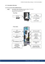
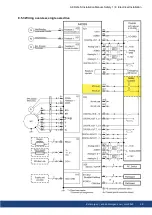
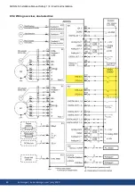
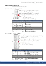
5. Check the wiring against the wiring diagrams:
Overview AKD2G single axis
Overview AKD2G dual-axis
Connector pinout
# 61) ff
Mains power supply:
# 68) ff
Logic power supply:
DC Bus Link:
External Regen Resistor:
Motor single cable connection:
Motor dual cable connection:
Motor Holding Brake:
Feedback Connection
Encoder emulation:
Electronic gearing:
Master Slave:
EtherNet Fieldbus interface:
CAN bus interface:
Service interface:
Digital and analog I/O:
Functional Safety option 1:
AKD2G-S Installation Manual, Safety 1 | 8 Electrical Installation
Kollmorgen | kdn.kollmorgen.com | July 2020
47

