11.4.1 Frame size, flange and shaft options
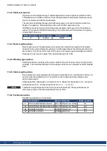
Dimension drawings can be found from page .
Framesize Flange
type
Flange
diameter
∅
Pilot
diameter
∅
Shaft
diameter
∅
Accuracy
pilot
1)
Accuracy
shaft
2)
Tolerance
class pilot
3)
2
A, C
79 mm
40 mm
11 mm
j6
k6
N
3
A, C
89 mm
60 mm
14 mm
j6
k6
N
4
A, C
114 mm
80 mm
19 mm
j6
k6
N
5
A, C
148 mm
110 mm
24 mm
j6
k6
N
6
A, C
186 mm
130 mm
32 mm
j6
k6
N
1) acc. to EN 60034-7……2) acc. to EN 42955……3) acc. to EN 50347
Flange mounting (flange types Ax, Bx):
The basic style for flange mounting is style IM B5 according to EN 60034-7.
Mount the FDA approved o-ring for flange sealing.
Face mounting (flange types Cx, Dx):
The basic style for face mounting is style IM B14 according to EN 60034-7.
Mount the FDA approved o-ring for flange sealing.
Shaft
Power transmission is made through the cylindrical shaft end (with a shaft center thread).
Code
Description
Description
C
Closed key way
Key way according to DIN 748.
Key according to DIN 6885 T1 form A.
Key material: stainless steel 1.4404
Shaft center locking thread
Shaft material: stainless steel 1.4404
N
Smooth shaft
Shaft center locking thread
Shaft material: stainless steel 1.4404
AKMH Installation | Table of Contents
Kollmorgen | March 2014
39
Summary of Contents for AKMH2
Page 62: ...18 4 Dimensions AKMH3 Ax flanges AKMH Installation Table of Contents 62 Kollmorgen March 2014...
Page 64: ...18 7 Dimensions AKMH4 Ax flanges AKMH Installation Table of Contents 64 Kollmorgen March 2014...
Page 66: ...18 10 Dimensions AKMH5 Ax flanges AKMH Installation Table of Contents 66 Kollmorgen March 2014...
Page 68: ...18 13 Dimensions AKMH6 Ax flanges AKMH Installation Table of Contents 68 Kollmorgen March 2014...
Page 73: ...AKMH Installation Kollmorgen March 2014 73...


