14.3 Wire color coding
Power lines
Brake lines
Feedback lines
Power
Color
Brake Color DSL
Color
SFD3 Color SFD
Color
U
blue
BR+
red
COM+ brown or
blue
DATA+ white DATA+ white
V
brown
BR-
blue COM-
white
DATA- brown DATA- brown
W
black
-
-
-
-
-
-
Up
red
PE
green/yellow
-
-
-
-
-
-
0V
blue
14.4 Guide for electrical installation
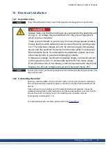
1. Check that the drive and motor match each other. Compare the rated voltage and rated
current of the unit.
2. If the motor must be connected to an AKD-B/P/T/M drive with 230V rated supply voltage
(AKD-xzzz06 types), then the ferrule tips supplied on motor power wires must be trimmed
by approximately 2 to 3 mm.
3. Ensure that there is proper earthing of the drive and the motor. Use correct earthing and
EMC-shielding according to the AKD installation manual. Earth the mounting plate and
motor housing.
4. The shielding must be connected to the drive (refer to the AKD installation manual).
5. Connect up all system shielding via a wide surface-area contact (low impedance) and met-
allized connector housings or EMC-cable glands.
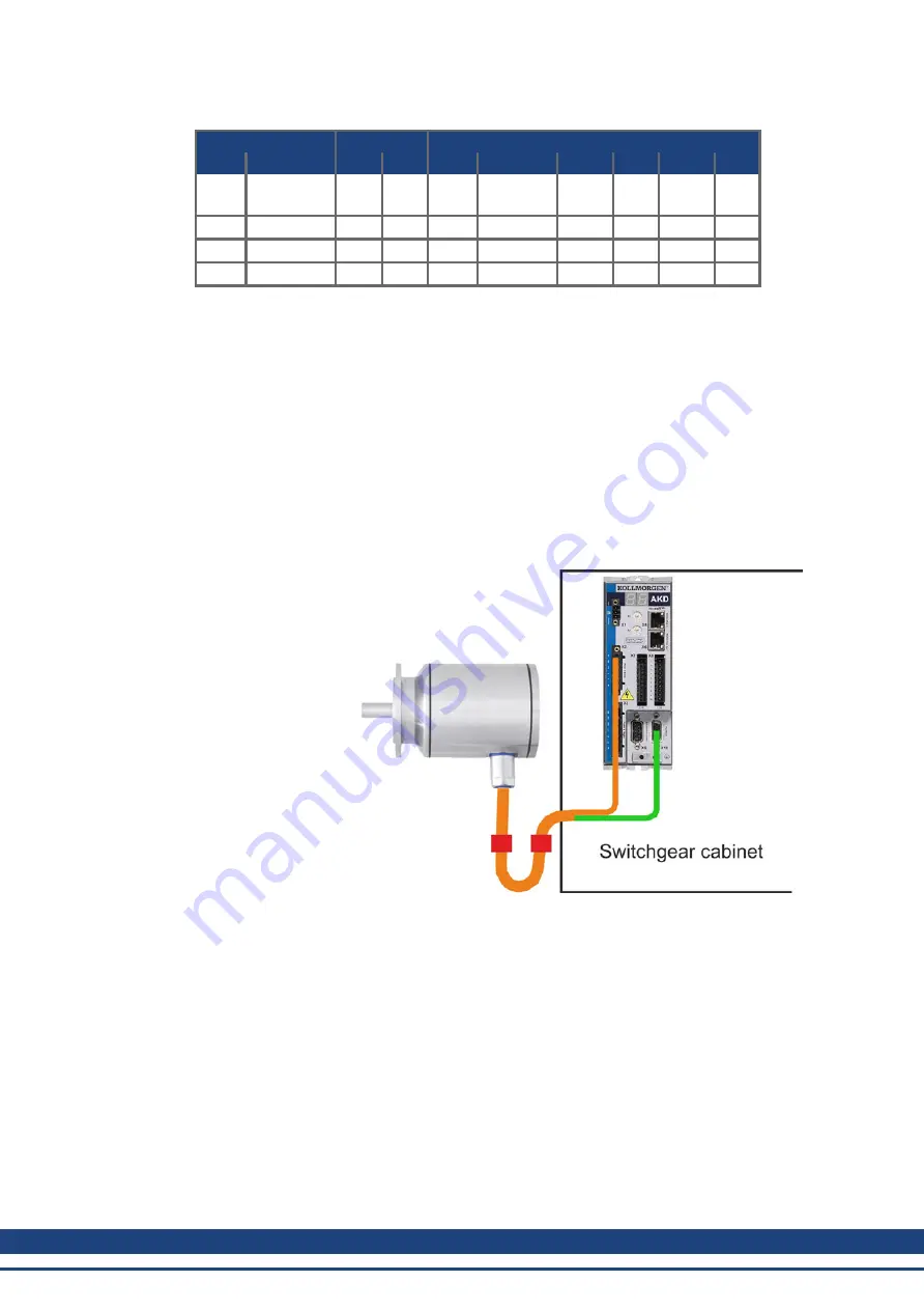
System with AKMH
and AKD-P
AKMH Installation | Table of Contents
50
Kollmorgen | March 2014
Summary of Contents for AKMH2
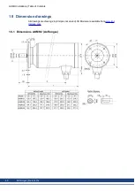
Page 62: ...18 4 Dimensions AKMH3 Ax flanges AKMH Installation Table of Contents 62 Kollmorgen March 2014...
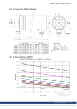
Page 64: ...18 7 Dimensions AKMH4 Ax flanges AKMH Installation Table of Contents 64 Kollmorgen March 2014...
Page 66: ...18 10 Dimensions AKMH5 Ax flanges AKMH Installation Table of Contents 66 Kollmorgen March 2014...
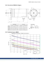
Page 68: ...18 13 Dimensions AKMH6 Ax flanges AKMH Installation Table of Contents 68 Kollmorgen March 2014...
Page 73: ...AKMH Installation Kollmorgen March 2014 73...

