P50330 Installation
│
Install
13
Kollmorgen | May 2012
13
Kollmorgen | April 2013
Wiring is application specific
Wiring sizes, wiring practices and grounding/shielding techniques described in the following
section represent common wiring practices and should prove satisfactory in the majority of
applications.
Non-standard applications, local electrical codes, special operating
conditions, and system configuration wiring needs take precedence
over the information included here. Therefore, you may need to wire
the drive differently then described here.
Electrical noise reduction
Use shielded and twisted cabling for the signal and power cables as described below. This
precaution reduces electrical noise.
Shock hazard reduction
Refer to section 2.1 for safety information that must be followed to reduce shock hazard.
2.5.1 Introduction
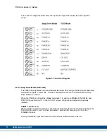
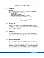
The P5000 has one 12-position terminal block for input power, motor power, and command
I/O. The terminal mating connector is a 2-piece modular connector. The two modules are for
power supply and motor power connection (terminals 1 through 6) and for control interface
connection (terminals 7 through 12). Each piece can be removed separately by pulling the
connector body upwards and off of the mating header pins on the P5000 drive.
The
connectors must initially be removed to mount the P5000 to a heatsink or chassis
.
Connector Diagram is shown below:


