background image

2


© 2020 Kolpin Outdoors Inc.


REV 00


OPERATING INSTRUCTIONS


Congratulations! You’ve just purchased the most durable accessory component in the industry. Our accessories work great all year 
round! With proper care and maintenance, your Kolpin accessory will last for years to come! Please read and understand all assembly 
instructions, notices and warnings before assembling and using your Kolpin accessory.


Follow these guidelines to ensure a successful and satisfactory installation:


Read, understand this manual before beginning installation 


Periodically check for wear and tightness of all fasteners. 


Replace or re

-

torque fasteners as necessary.


SAFETY & GENERAL PRODUCT INFORMATION


Kolpin accessories are designed with your safety in mind. 


In order to protect you and your vehicle, certain parts of the accessory and/or hardware may be designed to collapse or break when 
the equipment is over

-

stressed.


Kolpin winch mount kits are designed to be compatible with Kolpin and Cycle Country winches along with many others, but may not 
be compatible with some winches. Kolpin winch mount kits have design features that benefit snow plow applications. 


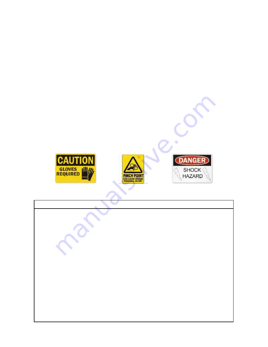
!  DANGER  !     !  WARNING !     !  CAUTION  !


To avoid personal injury or damage to your vehicle:


Read and understand all notices for:


Caution


Warning


Danger


Follow instructions for your vehicle, winch, winch mount and other items used in combination with this product.


Do not winch unsecured loads at any time.


Disconnect battery during winch installation or service to prevent electrical hazards.


Do not lift loads overhead.


Do not exceed the load capacity of the winch.


Always wear gloves when handling wire winch cable.


Do not use your winch or winch mount for towing.


Do not shock load the winch, cable or winch mount.


Keep fingers, hands and loose clothing away from roller fairlead and winch cable drum when in use.


Summary of Contents for 25-3410

Page 1: ...P N 25 3410 ASSEMBLY OWNERS MANUAL Application WINCH KIT NO 25 9xxx Before you begin please read these instructions and check to be sure all parts and tools are accounted for The following instruction...

Page 2: ...hardware may be designed to collapse or break when the equipment is over stressed Kolpin winch mount kits are designed to be compatible with Kolpin and Cycle Country winches along with many others but...

Page 3: ...Kolpin Outdoors Inc REV 00 Kit Contents Item Qty Part Description Part Number 1 1 Winch Bracket Weldment Sportsman ATV 2 4 Hex Flange Bolts Zinc Plated M8 1 25 x 25mm LG 3 1 Instruction Guide not sho...

Page 4: ...27 Torx Sportsman T40 Torx ACE Do not use impact tools to install hardware APPROXIMATE ASSEMBLY TIME 15 minutes Note If any hardware is missing do not return to the store Call us to help Toll Free 1 8...

Page 5: ...ve and keep nut from red positive battery cable and disconnect positive battery cable See illustration 1 2 5 Remove and keep four screws from lower front bumper cover as shown Remove lower front bumpe...

Page 6: ...11 Remove and keep four lower front bumper cover screws See illustration 1 9 12 Remove winch cover from lower front bumper cover You can keep it removed or trim as marked See illustration 1 10 Note b...

Page 7: ...14 17 Remove and discard two push pin rivets from winch cover Remove and discard winch cover as shown See illustration 1 15 Note before installing winch kit add or replace proper fluid to your vehicl...

Page 8: ...ll front grille guard WINCH ASSEMBLY 19 Install the roller fairlead and winch to the winch mounting bracket item 1 as shown Use the hardware included in the winch kit for this step Tighten to specific...

Page 9: ...illustration 1 19 2015 2020 SPMN 450 570 Install Winch to Mount 21 For 2015 2020 Sportsman 450 570 models To gain clearance access for installation of wiring the winch motor should be located on the l...

Page 10: ...n 1 22 WINCH ACCESSORY INSTALLATION 23 Install the winch mount assembly into the vehicle as shown Use the screws item 2 included in the mount kit for this step Tighten to specification See illustratio...

Page 11: ...t covers the main vehicle power wire 29 Put front bumper cover onto vehicle and identify area to be trimmed on both sides of bumper cover See illustration 1 25 30 Cut along marked lines 31 Install fro...

Page 12: ...ification 38 Lower front cover down slowly to engage tabs on cover into slots See illustration 1 29 39 Install four screws to front cover Tighten until fully seated See illustration 1 30 40 Install ru...

Page 13: ...black negative wires to the negative battery terminal Torque to specification See illustration 1 33 45 Install front storage bin and attach two fasteners See illustration 1 34 46 Install front bumper...

Page 14: ...ed by accident alteration abuse improper maintenance normal wear or other causes beyond the manufacturer s control In order to protect you and your ATV certain parts of the plow system and or hardware...

Reviews: