63
FIG-18. Engine Disassembly
TRANSMISSION & KICK STARTER
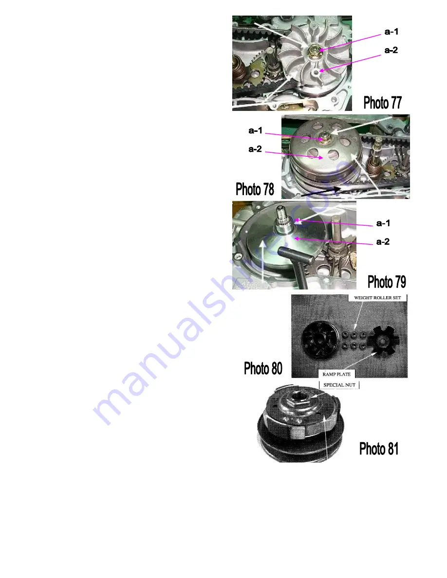
C.V.T REMOVAL
Relax the flange nut (a-1), and remove the drive face.
(a-2)
(Photo 77)
Relax the flange nut. (a-1)
Remove the drive pulley ass’y and driven belt. (a-2)
(Photo 78)
Remove the drive face boss (a-1) and movable driven
face ass’y. (a-2)
(Photo 79)
Remove the ramp plate and weight roller set
(Photo 80)
Relax the special nut and remove the driven plate
composition and driven face spring
(Photo 81)
Summary of Contents for 180??
Page 1: ...Kolpin Powersports 180cc Service Manual...
Page 7: ...5...
Page 19: ...17 0 6 0 7 mm...
Page 30: ...28 FIG 10 Front Brake BRAKE SYSTEM Brake Parts Location...
Page 40: ...38 0 6 0 7 mm...
Page 69: ...67...
Page 74: ...72 0 6 0 7 mm...
Page 86: ...84 0 6 0 7 mm...
Page 87: ...85 FIG 21 MAIN WIRING DIAGRAM...


