background image

Vers. 280519

8

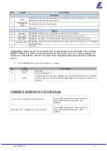
PIN

NAME

FUNCTION

OUTPUT

1

+24V

+24V voltage protected. The maximum  current  consumption is 400mA. CAN  NOT  BE
USED TO POWER EXTERNAL DEVICES.

2

GND

Common  pin.  Signals  must  be  taken  between  this  pin (GND) and  the  respective  signal
pins.

3

ERROR

Error signal: it activates every time an error occurs.
The red led on the front panel will switch on.
Signal is 24V.

4

MOTOR ON

(\W)

It activates when the motor turns during screwing. Signal is 24V.

5

SCREW OK

Correct screw signal. The green led on the front panel will switch on.
Signal is 24V.

INPUT

6

NOT USED

Not used

7

STOP

MOTOR

Remote  motor  stop.  If  it’s  activated  the  message  “STOP  MOTOR  ON”  appears  on  the
display.  The  motor  will  stop  and  won’t  start  working  again  as  long  as  the  contact  is

closed.

8

REVERSE

Remote motor start with torque control while unscrewing.

9

START

Remote start with torque control while screwing.

10

GND

Common pin. Signals must be taken between this pin and the respective signal pins.

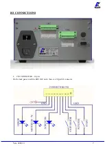
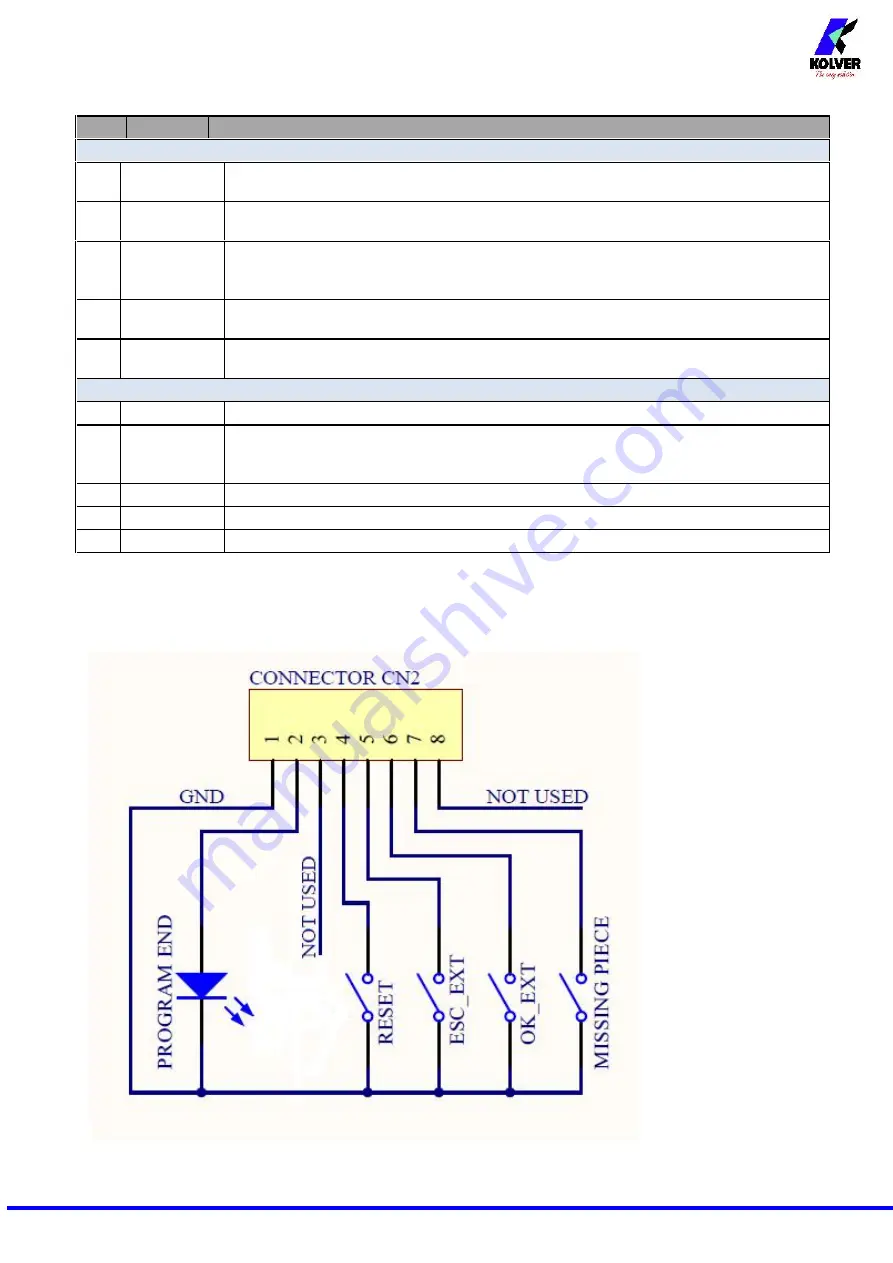
CN2 CONNECTOR

8 pin:

Summary of Contents for 032000/FR

Page 1: ...DECLARATION OF CONFORMITY KOLVER S r l declares that the new tool here described control unit model EDU 2AE FR is in conformity with the following standards and other normative documents 2006 42 CE LV...

Page 2: ...3 parameters voltage frequency and current according to the selected options The AC 90 260V 50 60Hz power supply is converted into 40VDC required by the PLUTO series screwdrivers through a switching b...

Page 3: ...nter the menu press ESC for 2 seconds Select the line by pressing or then press OK the symbol will turn into Press or to select the required value and then confirm through OK or ESC if you don t want...

Page 4: ...using this option with self tapping screws ATTENTION Reaching the torque while the ramp is still on will activate the screw OK signal anyway this option is useful if you need to tighten screws that a...

Page 5: ...the function select OFF by pressing as many times as needed ATTENTION During the reverse it is necessary to keep the lever or the start signal pressed as long as it won t stop Correct screw will be d...

Page 6: ...Press ESC when ON press ESC to reset the control unit When OFF the control unit resets automatically after an error signal INTERPRETATION OF ACOUSTIC SIGNALS The control unit emits sounds which help y...

Page 7: ...Vers 280519 7 I O CONNECTIONS CN1 CONNECTOR 10 pin On the back panel in all the EDU 2AE units there is a 10 pin I O connector...

Page 8: ...es when the motor turns during screwing Signal is 24V 5 SCREW OK Correct screw signal The green led on the front panel will switch on Signal is 24V INPUT 6 NOT USED Not used 7 STOP MOTOR Remote motor...

Page 9: ...utput signals are protected from an appropriate circuit Overload of the available signals 450 mA or short circuit will result in the stop of the unit To re activate signals it is necessary to switch o...

Page 10: ...y 12 Protection 12A is displayed on the status bar it happens when current on mosfets of bridge H is 12 A for at least 1 sec Reduce cycle rate and check settings Avoid motor stalling Unscrewing too he...

Page 11: ...correct or incorrect OK the torque has been correctly reached all the selected parameters are satisfied and the control unit will give out a beep sound of 0 5 sec NOK the torque has been reached durin...

Page 12: ...Vers 280519 12 EXPLODED VIEW EDU2AE FR...

Page 13: ...ront panel EDU2AE 1 818002 12 Connector M12 5 pin nut ferrite 1 201666 R1 13 Display EDU2AE 1 852522 14 Zn white nut M3 7 800056 15 Washer M3 5 800041 16 Plastic support 4 800016 B 17 Bottom panel EDU...

Page 14: ...ree of charge such items 3 This guarantee does not cover repair or replacement required as a consequence of products which have been abused misused or modified or which have been repaired using not or...

Reviews: