Vers. 111422
49
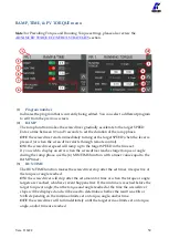
If the (7)
function is used, this will be the final tightening speed that the
screwdriver will downshift to after the selected “AT” threshold is reached.
For the reverse speed of the screwdriver, see the REV & PRE-REV. Note that you can
invert the tightening and untightening directions of rotation via the PROGRAMS >
OTHER menu.
(7)
DOWNSHIFT
The DOWNSHIFT function lets you execute the tightening in two phases: a high speed
approach (enter the speed in the “RPM” field), followed by a lower (6)
after a certain torque or angle threshold is reached.
OFF
(red): the screwdriver will run at the (6)
ON
(green): the screwdriver will run at the entered “RPM” speed until a certain torque
or angle is reached (AT torque/angle value), at which point it will downshift to the (6)
for the remainder of the tightening.
If using an angle threshold, the angle is counted in accordance with the
setting.
(8)
ANGLE CONTROL / TORQUE MONITORING flag
Tap to select Angle Control and Torque Monitoring mode.
In this mode, the screw is tightened down to the target angle (number of revolutions of
the screw, in degrees), while the torque is measured.
(9)
TARGET Angle
Tap to set the target angle. Only available in Angle Control/Torque Monitoring mode.
(10)
MIN Angle
If the angle measured at the end of the tightening is below the MIN Angle value, the
tightening will be considered unsuccessful (NOK) and a corresponding error will be
raised. Applicable to Torque Control as well as Angle Control modes.
(11)
MAX Angle
If the angle measured at the end of the tightening exceeds the MAX Angle value, the
tightening will be considered unsuccessful (NOK) and a corresponding error will be
raised. Applicable to Torque Control as well as Angle Control modes.
(12)
STARTING AT
Tap to select the starting point for the angle measurement. Three modes are available:
-
Torque threshold
: the angle measurement starts after the torque reaches this value
-
Lever
: the angle measurement starts as soon as the screwdriver level is pressed
-
Ext In
: the angle measurement starts after the IN-ANG external I/O signal is received
(13)
Exit/Save key
Tap to return to the previous menu and save or discard any changes made.
Summary of Contents for 033001
Page 1: ...KDU NT and KDS NT Torque range 5 70 cNm 7 100 ozfin OPERATOR MANUAL Patent pending...
Page 13: ...Vers 111422 13 Threaded M3 fixturing holes side holes on CA models only...
Page 44: ...Vers 111422 44 PROGRAMS menu tree...
Page 45: ...Vers 111422 45...
Page 46: ...Vers 111422 46...
Page 47: ...Vers 111422 47...
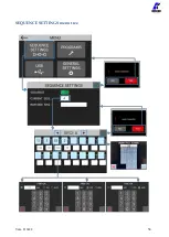
Page 58: ...Vers 111422 58 SEQUENCE SETTINGS menu tree...
Page 68: ...Vers 111422 68 USB menu tree...
Page 72: ...Vers 111422 72 Pinout CN5...
Page 83: ...Vers 111422 83 EXPLODED VIEW KDS NT70 KDS NT70 HM...
Page 84: ...Vers 111422 84...
Page 85: ...Vers 111422 85...
Page 86: ...Vers 111422 86 SPARE PARTS KDS NT70 KDS NT70 HM Lever Kit HM Half Moon model...
Page 87: ...Vers 111422 87 EXPLODED VIEW KDS NT70CA KDS NT70CA HM...
Page 88: ...Vers 111422 88 SPARE PARTS KDS NT70 KDS NT70 HM...


