background image


Vers. 072821 


11 

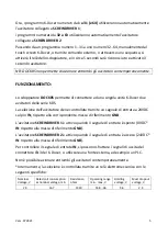
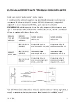
CN3. Some 

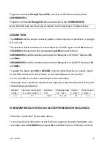
examples are provided below. Refer to “I/O Connections” section of the 

K-Ducer manual to devise further selection schemes. 

DOCK05 
Pin GND 
wired to: 

DOCK05  
Pin IN  
wired to: 

SCREWDRIVER 1 
active with: 

SCREWDRIVER 2 
active with: 

KDU CN3 
Pin 44 (GND) 

KDU CN3 Pin 35 
(DOCK05) 

K-Ducer current program     
1 through 31, and 64 

K-Ducer current program  
32 through 63 

KDU CN3 Pin 27 
(BIT3SQ) 

K-Ducer current sequence  
A, B, C, H 

K-Ducer current 
sequence  D, E, F, G 

KDU CN3 Pin 28 
(BIT1PR)* 

K-Ducer current program 
even # (2,4,6,..,62,64) 

K-Ducer current program 
odd # (1,3,5,..,61,63) 


*BITxPR pins cannot be used if: sequence mode is active and 

“remote prg” 

is active, or 

sequence mode is active and switchbox accessory is active in “on prg” mode


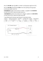
SCREWDRIVER SELECTION VIA PLC OR OTHER EXTERNAL SOURCE: 


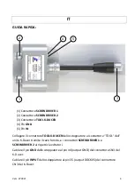
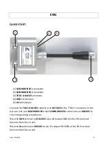
Connect the 

TOOL K-DUCER

 connector on 

DOCK05


to the “TOOL” connector on the 

K-Ducer unit, and 

SCREWDRIVER 1

 and 

SCREWDRIVER 2

 connectors on 

DOCK05

 to 

the corresponding screwdrivers. 

Summary of Contents for DOCK05

Page 1: ...standards and other normative documents 2006 42 CE LVD 2014 35 UE EMCD 2014 30 UE EN 62841 2 2 2014 EN 62841 1 2015 EN 60204 1 EN 61000 6 1 EN 61000 6 3 conforme alla direttiva RoHS III 2011 65 UE e s...

Page 2: ...Vers 072821 2 Manuale Istruzioni Operator s Manual DOCK05 KOLVER S r l VIA MARCO CORNER 19 21 36016 THIENE VI ITALIA TEL 39 0445 371068 www kolver it...

Page 3: ...mento 5 Selezione Avvitatore Tramite Programmi o Sequence K Ducer 6 Selezione Avvitatore Tramine Fonte Esterna PLC 7 Garanzia 8 English 9 13 Quick Start 9 Description 10 Screwdriver Selection Via K Du...

Page 4: ...OOL K DUCER dello sdoppiatore al connettore TOOL dell unit K Ducer tramite il cavo fornito e i connettori SCREWDRIVER 1 e SCREWDRIVER 2 ai rispettivi avvitatori Cablare il pin GND dello sdoppiatore al...

Page 5: ...selezione dell avvitatore viene controllata tramite un segnale di entrata a 24VDC sul pin IN rispetto alla corrispondente massa di riferimento GND L avvitatore SCREWDRIVER 1 attivo quando il segnale...

Page 6: ...er sezione Connessioni I O per progettare altri schemi di controllo DOCK05 Pin GND cablato a DOCK05 Pin IN DOCK05 cablato a SCREWDRIVER 1 attivo con SCREWDRIVER 2 attivo con KDU CN3 Pin 44 GND KDU CN3...

Page 7: ...e il segnale GND dello sdoppiatore alla massa del corrispettivo segnale di uscita sourcing del PLC o altra fonte esterna Mantenendo attivo il segnale di uscita sourcing a 24VDC verr selezionato l avvi...

Page 8: ...dei materiali 3 Questa garanzia non valida per quei prodotti che sono stati usati in modo non conforme o modificati o che non sono stati riparati da KOLVER o perch sono stati utilizzati ricambi non o...

Page 9: ...ER connector on DOCK05 to the TOOL connector on the K Ducer unit and SCREWDRIVER 1 and SCREWDRIVER 2 connectors on DOCK05 to the corresponding screwdrivers Wire the GND terminal on DOCK05 to pin 44 ou...

Page 10: ...whenever the IN signal is on 24VDC between IN and GND To power the input signal IN on DOCK05 one can utilize the K Ducer output signals on the CN3 connector of the K Ducer or an external source such...

Page 11: ...Pin 27 BIT3SQ K Ducer current sequence A B C H K Ducer current sequence D E F G KDU CN3 Pin 28 BIT1PR K Ducer current program even 2 4 6 62 64 K Ducer current program odd 1 3 5 61 63 BITxPR pins cann...

Page 12: ...plied to the DOCK05 IN terminal from the PLC output pin output signal on SCREWDRIVER 1 will be active whenever no voltage is supplied to the DOCK05 IN terminal from the PLC output pin output signal of...

Page 13: ...ree of charge such items 3 This guarantee does not cover repair or replacement required as a consequence of products which have been abused misused or modified or which have been repaired using not or...

Page 14: ...Vers 072821 14 Dimensioni Dimensions...

Reviews: