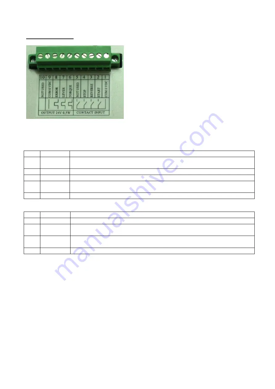
I/O CONNECTION
On the back panel you’ll find only one connector I/O 10 pins which must be connected to the 90°
connector coming from the unit.
INPUT:
PIN
FUNCTION
1
COM 0VDC Common pin. By closing the contact between pin 1 and any of the other pins ( 2, 3, 4, 5)
to start the function you need.
2
START
Remote start. Clockwise. Torque control.
3
REVERSE
Reverse remote start. Counterclockwise. No torque control
4
STOP
Stop motor. “STOP ACTIVE”screen. Motor stops and starts again after the contact has
opened.
5
NOT USED Only used in special versions.
OUTPUT:
PIN
FUNCTION
6
TORQUE
Torque reached signal. Signal is 24V 20 mA , max 0,5W.
7
LEVER
Lever signal: when lever is pressed or when the start is remote. No signal during
unscrewing cycle. It resets after their release. Signal is 24V 20 mA , max 0,5W.
9
COM0VDC Common pin for any output. Signals must take between pin 1 ( 0VDC common) and the
other pins (6,7 and 8).
10
NOT USED Only used for special versions.
Output signals are protected. Overload of
these 3 available signals (> 60 mA) or short circuit will result
in the stop of the unit. To re-activate signals, i
t is necessary switch off the unit for 5-6 seconds, check
connections outputs then switch on the unit.
BIP SOUNDS
Bip sounds at the end of the screwing allow to check if the screwing itself is correct or not.
A screwing results correct when the torque has been reached satisfying all the settings (0,5 sec bip
sound). Torque reached during Ramp or Brake Time (only on hard joint) will result 3 bip sounds.
NB
. Torque reached during Ramp or Brake Time will result in torque reached signal. For Brake
Time only in error signal also.


