background image

EN

WARNING: To reduce the risk of injury, before using or servicing tool, read and
understand  the  following  information  as  well  as  separately  provided  safety
instructions (Item number: 0MS000). The features and descriptions of our products
are subject to change without prior notice.

1. Applications

KOLVER electric  screwdrivers  are  used  to  tighten  to  the  required  torque  screws,
nuts, studs and any other kind of threaded connection on any material. Obviously,
it  is  possible  to  use  the  screwdrivers  with  screw  having  a  larger  diameter  if  the
torque  fall  within the  indicated  range.  All  models  are  reversible  and  can
consequently  be  used  to  unscrew.  Electric  screwdrivers  are  mainly  used  in  the
electronic industry as well as for electric appliances, wiring, toys, lamps, glasses, in
the mechanical light industry etc.

2. Use

KOLVER  screwdriving  system  is  composed  by  a  screwdriver,  a  cable  with  2  x
M12  female  5  pin  connectors  and  a  power  supply  and  control  unit.  To  install  it
please follow the instructions.

a) Connect  the  5-pin  connectors  of  the  cable  to  the  controller  and  to  the
screwdriver and tighten the relevant nuts.
b) Connect the controller plug to a mains supply socket 90 / 230V- 50/60Hz.
c) Switch the controller on through the black button on the back panel.
d) Select  the  desired  setting  of  speed  (A)  and  slow  start  (R)  options  through  the
relevant knobs. Please make sure that such settings are compatible with the torque
setting. Since the speed reduction is obtained through a voltage reduction (= power
reduction), if the torque setting is too high for a low speed setting, the clutch may
not operate correctly and get stuck. In such a case, the driver will not run and when
you press the start lever the red light will signal. To reset the driver just turn the bit

chuck  until  you hear the clutch  “click” (usually

180°).  Increase the speed setting

before running the driver again.
e) Similarly,  the  slow  start  setting  should  be  chosen  according  to  the  torque  that
must be reached at full speed and not when the slow start is still in action.
g) Do not slide the forwar

d/reverse  while the  motor is running, it’s dangerous  for

the motor.

Summary of Contents for FAB03SS/FR

Page 1: ...FAB18RE FR 110618 FR RAF38PP FR 120639 FR FAB18PS FR 112618 FR RAF38PP FR U 120639 FR U FAB18PP FR 110619 FR FAB18PP FR U 110619 FR U EDU1FR 010010 FR EDU1FR SG 010010 FR SG G È conforme alle disposizioni legislative che traspongono le direttive Is in conformity with the following standards and other normative documents 2006 42 CE 2006 95 CE 2004 108 CE EN 60745 1 EN 60204 1 EN 61000 6 1 EN 61000 ...

Page 2: ...le Istruzioni Operator s Handbook FAB RAF Avvitatori Screwdrivers EDU1FR EDU1FR SG Unità di controllo Control unit KOLVER S r l VIA MARCO CORNER 19 21 36016 THIENE VI ITALIA TEL 39 0445 371068 www kolver it ...

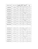
Page 3: ...50 Leva Lever 226 x 36 FAB18PS FR 112618 FR 0 3 1 8 650 Pressione Push 220 x 33 FAB18PP FR 110619 FR 0 3 1 8 650 Leva Lever 200x150x34 FAB18PP FR U 110619 FR U 0 3 1 8 650 Leva Lever 200x150x34 RAF32NS FR 120032 FR 0 7 3 2 1000 Leva Lever 247 x 40 RAF32PS FR 122032 FR 0 7 3 2 1000 Pressione Push 247 x 40 RAF32PP FR 120033 FR 0 7 3 2 1000 Leva Lever 200x150x40 RAF32PP FR U 120033 FR U 0 7 3 2 1000 ...

Page 4: ...edere all utilizzo operare come segue a Collegare il connettore a 5 contatti del cavo dell avvitatore alla presa dell unità di alimentazione e serrare la ghiera relativa b Inserire la spina dell alimentatore in una presa di corrente vedi dati tecnici c Accendere l alimentatore premendo l apposito pulsante sul pannello posteriore d Procedere all avvitatura assicurandosi che la velocità e la rampa i...

Page 5: ...ll avvitatore tramite un sofisticato regolatore switching da 120W Il circuito elettronico di controllo arresta istantaneamente l alimentazione di corrente al motore dell avvitatore al raggiungimento della coppia prefissata Sul pannello frontale sono presenti due manopole R e A R indica la rampa di accelerazione regolabile da 0 a 2 sec e la velocità A indica la velocità dell avvitatore regolabile d...

Page 6: ...i di coppia e leva premuta 24V 20mA OUTPUT INPUT NOT USED 5 6 7 4 3 2 1 COM M ON 0 VDC START M OTOR LEVER SIGNAL TORQUE SIGNAL N O REVERSE STOP M OTOR 24V 20mA CONTACT PIN 1 2 CONTACT PIN 1 3 CONTACT PIN 1 4 SIGNAL PIN 5 O VDC PIN 1 SIGNAL PIN 6 O VDC PIN 1 PIN 1 massa comune COM 0Vdc PIN 2 tramite contatto tra pin 1 e 2 l avvitatore avvita con controllo di coppia in senso orario PIN 3 tramite con...

Page 7: ...ilizzo continuo alla massima coppia nominale si tradurrà in una prematura usura delle spazzole in carbone della molla della frizione e della frizione superiore L uso continuo oltre l 80 del campo di coppia non è raccomandato NOTE Il livello di pressione acustica continuo equivalente ponderato è sempre inferiore a 70dB A Il braccio dell utilizzatore è esposto ad una accelerazione media ponderata in...

Page 8: ...eriali 3 Questa garanzia non è valida per quei prodotti che sono stati usati in modo non conforme o modificati o che non sono stati riparati da KOLVER o perché sono stati utilizzati ricambi non originali KOLVER o perché riparati da persone non autorizzate da KOLVER 4 KOLVER non accetta nessuna richiesta di risarcimento per spese di manodopera o di altro tipo causate da prodotti difettosi 5 Si escl...

Page 9: ...stall it please follow the instructions a Connect the 5 pin connectors of the cable to the controller and to the screwdriver and tighten the relevant nuts b Connect the controller plug to a mains supply socket 90 230V 50 60Hz c Switch the controller on through the black button on the back panel d Select the desired setting of speed A and slow start R options through the relevant knobs Please make ...

Page 10: ...supply to the motor in response to the clutch action as soon as the pre set torque has been reached On the front panel of the controller there are two knobs indicated with the letters R and A Knob R is used to adjust the slow start option ramp from 0 to 2 seconds i e the motor will reach the nominal speed gradually Dial 1 for no ramp and 10 for maximum ramp Knob A is used to adjust the motor speed...

Page 11: ...g OUTPUT INPUT NOT USED 5 6 7 4 3 2 1 COM M ON 0 VDC START M OTOR LEVER SIGNAL TORQUE SIGNAL N O REVERSE STOP M OTOR 24V 20mA CONTACT PIN 1 2 CONTACT PIN 1 3 CONTACT PIN 1 4 SIGNAL PIN 5 O VDC PIN 1 SIGNAL PIN 6 O VDC PIN 1 PIN 1 earth common COM 0Vdc PIN 2 contact between pin 1 and 2 Clockwise PIN 3 contact between pin 1 and 3 Counterclockwise PIN 4 contact between pin 1 and 4 it stops the motor ...

Page 12: ... Kolver dealer or repair centre Always remember to switch off the control unit at the end of each working shift Using a screwdriver at the max torque rated will result in a premature wear out of carbon brushes clutch spring and upper clutch Continuous use over 80 of torque range is not recommended NOTE The sound level generated by Kolver electric screwdrivers is always lower than 70dB A The vibrat...

Page 13: ... charge such items 3 This guarantee does not cover repair or replacement required as a consequence of products which have been abused misused or modified or which have been repaired using not original KOLVER spare parts or by not authorized service personnel 4 KOLVER accepts no claim for labour or other expenditure made upon defective products 5 Any direct incidental or consequential damages whats...

Page 14: ......

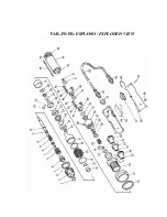
Page 15: ...FAB RE FR ESPLOSO EXPLODED VIEW ...

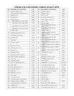
Page 16: ...g 200013 Ingranaggio satellite Planet gear FAB03 FAB18 3 210244 14 Anello elastico Circlip 211014 47 Ingranaggio motore Main gear FAB10 FAB12 210147 15 Molla Spring 211015 Ingranaggio motore Main gear FAB03 FAB18 210247 16 Guarnizione Ring 211016 50 Testa motore Motor head 210050 17 Bussola porta micro Buffer cone 211017 51 Motore Motor 210051 18 Gancio microinterruttore Hook 201018 Motore Motor F...

Page 17: ...FAB PS FR ESPLOSO EXPLODED VIEW ...

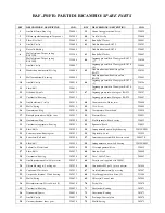
Page 18: ...anaggio motore Main gear FAB03 FAB18 210247 15 Molla Spring 202015 50 Testa motore Motor head 210050 16 Guarnizione Ring 202016 51 Motore Motor 210051 17 Bussola porta micro Buffer cone 202017 52 Molla spazzola Brush spring 210052 20 Guarnizione Ring 202020 53 Spazzola Brush 210053 21 Cuscinetto reggispinta Bearing 202021 54 Impugnatura dx nera Right housing 210154 ESD 22 Sfere Balls 202022 55 Cop...

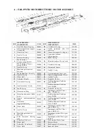
Page 19: ...g trigger 221061 6 Connettore Connector 5 pin M 231666 7 Portaconnettore Connector seat 234506 8 Cavo Cable 5 pin 2 5mt 200063 9 Impugnatura sx Left housing 234502 ESD 10 Vite Screw M3 x 6 TS 2 801002 11 Micro interruttore Micro switch 201056 12 Interruttore reversibilità Reverse switch 200057 S 13 Gancio Hook 200060 14 Vite impugnatura Screw 210059 15 Impugnatura dx Right housing 234501 ESD A Mot...

Page 20: ...1012 41 Rondella Washer 200041 13 Cuscinetto Bearing 200013 42 Gabbia riduzione Reduction plate FAB12 210142 14 Anello elastico Circlip 211014 Gabbia riduzione Reduction plate FAB18 210242 15 Molla Spring 211015 43 Rondella Washer 8 210043 16 Guarnizione Ring 211016 44 Ingranaggio satellite Planet gear FAB12 3 210144 17 Bussola porta micro Buffer cone 211017 Gabbia riduzione Reduction plate FAB18 ...

Page 21: ...RAF NS FR ESPLOSO EXPLODED VIEW ...

Page 22: ...14 Anello elastico Circlip 221014 47 Ingranaggio motore Main gear RAF32 220347 15 Molla Spring 221015 Ingranaggio motore Main gear RAF38 220447 16 Guarnizione Ring 221016 48 Giunto Motor joint 220048 17 Bussola porta micro Buffer cone 221017 49 Vite Screw 220049 18 Gancio microinterruttore Hook 201018 50 Testa motore Motor head 220050 19 Vite Screw 201019 51 Motore Motor 220051 20 Guarnizione Ring...

Page 23: ...RAF PS FR ESPLOSO EXPLODED VIEW ...

Page 24: ...Vite Screw 220049 16 Guarnizione Ring 202016 50 Testa motore Motor head 220050 17 Bussola porta micro Buffer cone 202017 51 Motore Motor 220051 20 Guarnizione Ring 202020 52 Molla spazzola Brush spring 220052 21 Cuscinetto reggispinta Bearing 202021 53 Spazzola Brush 220053 22 Sfere Balls 202022 54 Impugnatura dx nera Right housing 220354 ESD 23 Sede cuscinetto Bearing seat 202023 55 Coperchio Cov...

Page 25: ...ng trigger 221061 6 Connettore Connector 5 pin M 231666 7 Portaconnettore Connector seat 234506 8 Cavo Cable 5 pin 2 5mt 200063 9 Impugnatura sx Left housing 234502 ESD 10 Vite Screw M3 x 6 TS 2 801002 11 Micro interruttore Micro switch 201056 12 Interruttore reversibilità Reverse switch 200057 S 13 Gancio Hook 200060 14 Vite impugnatura Screw 210059 15 Impugnatura dx Right housing 234501 ESD A Mo...

Page 26: ...ne Reduction plate RAF32 220342 12 Alberino Spindle 221012 Gabbia riduzione Reduction plate RAF38 220442 13 Cuscinetto Bearing 200013 43 Rondella Washer 6 220043 14 Anello elastico Circlip 221014 44 Ingranaggio satellite Planet gear RAF32 3 220344 15 Molla Spring 221015 Ingranaggio satellite Planet gear RAF38 4 220444 16 Guarnizione Ring 221016 45 Gabbia riduzione Reduction plate RAF32 220345 17 B...

Page 27: ...5 PIN M12 M 201666 CS 9 Fusibile rapido Fuse 3 15 A 800619 3 Vite autofil Self tapping screw 2 6 x 9 5 12 800605 10 Presa con portafusibile Socket with fuseholder 230V 800618 4 Piedino plastica Plastic support 4 800016 11 Scheda PCB Main board 856806 B 5 Vite Screw M4 x 4 mm 806635 12 Foglio isolante Isolating sheet 800653 6 Contenitore Box 811010 VB 13 Pannello anteriore Front panel 821604 7 Pann...

Page 28: ...6 CS 9 Fusibile rapido Fuse 3 15 A 800619 3 Vite autofil Self tapping screw 2 6 x 9 5 12 800605 10 Presa con portafusibile Socket with fuseholder 230V 800618 4 Piedino plastica Plastic support 4 800016 11 Scheda PCB Main board 856806 T 5 Vite Screw M4 x 4 mm 806635 12 Foglio isolante Isolating sheet 800653 6 Contenitore Box 811010 VB 13 Pannello anteriore Front panel 821604 7 Pannello posteriore B...

Reviews: