background image


Vers. 062721


71


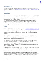
Binary tables for sequence and program selection


Refer to the tables below for sequence or program selection via CN3, where “1” refers to an 
24VDC signal with respect to the GND pin and “0” refers to no signal.


The REMOTE PR or REMOTE SEQ setting (General Settings > 

REMOTE PR

 and 

REMOTE 

SEQ

 ) must be active for the input selection to work.


The outputs pins 25-33 will always be active irrespective of the REMOTE PR/SEQ setting, 
following the same binary code pattern for the input side reported below.


Sequence


BIT3 SEQ


PIN 5


BIT2 SEQ


PIN 4


BIT1 SEQ


PIN 3


-


0


0


0


A


0


0


1


B


0


1


0


C


0


1


1


D


1


0


0


E


1


0


1


F


1


1


0


G


1


1


1


H


Not Selectable 


Summary of Contents for K-DUCER

Page 1: ...KDU1 KDU1A Torque range 0 1 70 Nm OPERATOR MANUAL...

Page 2: ...DECLARATION OF CONFORMITY KOLVER S r l declares that the new tool here described control units model KDU 1 KDU 1A are in conformity with the following standards and other normative documents 2006 42 C...

Page 3: ...Program Mode navigation tree 22 Main Screen Sequence Mode 23 Main Screen Sequence Mode navigation tree 25 Retrieving and storing the screwdriving results 26 Connecting a barcode scanner 28 Connecting...

Page 4: ...Introduction 64 Pinout CN3 65 Wiring diagrams 69 Binary tables for sequence and program selection 71 MODBUS TCP 73 Introduction 73 Usage 73 K DUCER MODBUS map 74 MODBUS TCP code examples and literatu...

Page 5: ...t the screwdriver motor works efficiently Read the menu description carefully and if unsure please contact Kolver for support MODELS K DUCER power supply and control units are available in two version...

Page 6: ...00 135015 KDS PL15 0 5 15 50 320 135015 ESD KDS PL15 0 5 15 50 320 135016 ESD KDS PL15P 0 5 15 50 320 135016 U ESD KDS PL15P U 0 5 15 50 320 135115 KDS PL15CA 0 5 15 50 320 135115 FN KDS PL15CA FN 0 5...

Page 7: ...Vers 062721 7 INSTALLATION Installation of KDU unit The K DUCER is supplied with the following mounting bracket all dimensions reported in mm...

Page 8: ...fixed to the four provided 8mm depth female threads on the back panel using the provided M4x8 screws Also available separately table stand part number 010400 vertically and horizontally adjustable br...

Page 9: ...onality such as PLCs pedals buttons LEDS etc Refer to REMOTE CONTROL INTERFACES chapter CN5 ethernet connector RJ45 To connect using MODBUS TCP Open Protocol or K Expand on any compatible device or so...

Page 10: ...it 2 turn the OPEN CLOSE nut counterclockwise 3 pull the connector out note some models use a threaded nut instead of an OPEN CLOSE nut In this case tighten the nut all the way until it stops without...

Page 11: ...ove also provide four threaded M4 holes for fixing to a custom assembly Warning do not connect the reaction arm anywhere other than the above designated areas Fixing the reaction arm to the middle of...

Page 12: ...Vers 062721 12 CA automation versions Reaction arm connection for KDS series screwdrivers 20Nm and above CA automation versions...

Page 13: ...r if no screwdriver is connected You can still enter the main menu without any screwdriver connected When a screwdriver is connected it will be recognized by the unit and the CONNECTED SCREWDRIVER scr...

Page 14: ...limit allowed for the screwdriver DownshiftTorqueOverTarg The fast phase torque setting is higher than the final target torque DownshiftSpeedOverMax The speed of the slow phase of this program is high...

Page 15: ...this program is higher than the maximum torque of the screwdriver RevSpeedOverMax The reverse speed is higher than the maximum allowed by the screwdriver RevSpeedUnderMin The reverse speed is lower th...

Page 16: ...the screwdriver system will apply in the rundown torque control mode only resulting in a Screw OK result if successful Prevailing torque an optional phase of the rundown during which the applied torq...

Page 17: ...rogram Sequence Job an ordered set of up to 16 programs with the option to define how to transition between programs Sequence letter number the identifier of one of the 8 configurable sequences A to H...

Page 18: ...perly sized reaction arm may result in severe injury or death The screwdriver will automatically stop according to the configured program in either an OK or a NOK state depending on the success of the...

Page 19: ...ast screw result was NOK Solid blue screwdriver is running in the tightening direction either via the lever or via remote control Solid purple the screwdriver is running in the de fix direction either...

Page 20: ...tton Tap to enter the main menu 4 Angle value Measured angle value for last screw in degrees 5 Angle target Shows the target angle when in angle control mode or the min max angle bounds when in torque...

Page 21: ...ror messages ready screw OK screw NOK errors 11 Torque target Shows the target torque when in torque control mode or the min max torque bounds when in angle control mode or timed rundown mode for the...

Page 22: ...Vers 062721 22 Main Screen Program Mode navigation tree...

Page 23: ...alue for last screw in degrees 5 Angle target Shows the target angle when in angle control mode or the min max angle bounds when in torque control mode or timed rundown mode for the current program in...

Page 24: ...torque control mode or the min max torque bounds when in angle control mode or timed rundown mode for the current program 12 Torque value Measured torque value applied to the last screw 13 Current an...

Page 25: ...Vers 062721 25 Main Screen Sequence Mode navigation tree...

Page 26: ...tained Via serial printer or serial terminal CN2 or CN4 You can connect to CN2 CN4 with a serial printer for example Kolver model PRNTR1 or with any serial terminals for example Hyper Terminal Realter...

Page 27: ...te time of the rundown 18 01 18 17 44 50 Notes or Errors Notes such as PROGRAM END for OK results or error details such as Err Angle Max for NOK results PROGRAM END or Err Angle Max For example BC 761...

Page 28: ...al power supply when using the RS 232 interface See BARCODE MODE for information on the three barcode working modes available and how to use them Connecting Kolver accessories SWBX88 CBS880 To utilize...

Page 29: ...positions 1 to 8 To use the accessories for sequence selection instead of program selection first activate SEQUENCE toggle then select On Seq instead of On Prog in the general settings menu field SWBX...

Page 30: ...p to 64 different programs 3 Touch to enter the general settings menu to configure general parameters such as passcode lock I O and MODBUS settings kolver accessories language etc 4 Touch to enter the...

Page 31: ...up to 64 different programs as well as assign a barcode to each for automatic selection with a barcode scanner Tap the Programs button from the main menu to enter the programs menu Select one of 64 p...

Page 32: ...Vers 062721 32 PROGRAMS menu tree...

Page 33: ...Vers 062721 33...

Page 34: ...Vers 062721 34...

Page 35: ...t or over 80 of the screwdriver s nominal torque range is not recommended 4 MAX Torque If the torque measured at the end of the rundown exceeds the MAX Torque value the rundown will be considered unsu...

Page 36: ...OFF red the screwdriver will run at the 6 FINAL SPEED for the entire rundown If ON green the screwdriver will run at the entered RPM speed until a certain torque is reached AT torque value at which po...

Page 37: ...OFF the screwdriver starts immediately turning at the target SPEED when the lever is pressed or when the screwdriver starts through remote control If ON the screwdriver speed will ramp up to the targ...

Page 38: ...counting from the moment the lever is pressed or a remote start signal is received If OFF this functionality is disabled 6 PREVAILING TORQUE The PREVALING TORQUE function makes the screwdriver work a...

Page 39: ...nctions If you re using an open end wrench attachment the reverse torque should be set to MIN value in order to bring the wrench back to the correct position 4 PRE TIGHTENING REVERSE This function mak...

Page 40: ...AFTER TORQUE phase The TORQUE and ANGLE results displayed at the end of the AUTO REVERSE AFTER TORQUE phase will correspond to the torque angle results from the tightening phase and not those from the...

Page 41: ...olver accessory 7 BARCODE Tap to enter the SCAN BARCODE screen to assign a barcode to the current program being edited To be used in conjunction with the BARCODE MODE ON PRG in the GENERAL SETTINGS me...

Page 42: ...tiplied by this factor For example if a torque value of 3 Nm is displayed with the COMPENSATION setting at 1 but you measure an effective torque value of 3 03 Nm with an external measurement tool you...

Page 43: ...to enter the sequence edit menu for one of 8 sequences A through H The sequence shown in the CURRENT SEQ input field corresponds to the pre selected sequence in the main screen You can also select a...

Page 44: ...Vers 062721 44 SEQUENCE SETTINGS menu tree...

Page 45: ...river will remain disabled until the transition timer completes The timer begins counting as soon as the program is completed even if the lever is not depressed or the remote start command is not remo...

Page 46: ...n the parameters of a single program WARNING use this transition setting with care and only when strictly necessary as the operator will not have any time to react to the program change 4 Exit Save Ke...

Page 47: ...ed by the screwdriver Also see MAINTENANCE AND CARE section TEMPERATURE the temperature measured near the motor of the screwdriver in degrees C Note exceeding a temperature of 40 C will put the screwd...

Page 48: ...EXT external to only allow these inputs to be received via external signals on the CN3 connector Choose INT EXT to allow the OK ESC RESET commands from both the touch screen display and the external...

Page 49: ...number containing the matching SWBX88 CBS880 setting Programs Other SWBX88 CBS880 ON SEQ the position selected on the accessory will load the corresponding sequence This sequence letters are matched...

Page 50: ...if applicable You can leave this as 0 0 0 0 in most cases DNS the ethernet IP address of the local DNS server You can leave this as 0 0 0 0 in most cases SUBNET MASK the subnet mask of the local netwo...

Page 51: ...se the USB type A port for this function not the mini USB port Note the USB drive must be formatted with the FAT32 filesystem If there is no USB drive connected or if the USB drive is not formatted wi...

Page 52: ...DUCER units or onto the freely available K EXPAND software for PC 3 DELETE programs button Tap to display a list of KDU files found in the root directory of the USB drive Select a file the selected f...

Page 53: ...Vers 062721 53 USB menu tree...

Page 54: ...unit The parameters that are displayed are the same as those inside the K DUCER unit and have the same functions warnings and limits described in this manual Interface Selection To connect the K DUCE...

Page 55: ...d and the K DUCER to the same LAN network or directly to each other then enter the K DUCER IP address in the corresponding K Expand field Screwdriver Once the screwdriver is connected to the K DUCER K...

Page 56: ...r de activating the SEQUENCE toggle on the K DUCER 2 Nr Program the current selected program on the K DUCER for program mode 3 Nr Sequence the current selected sequence on the K DUCER for sequence mod...

Page 57: ...to 16 programs each You must select the position of each program and the transition to move from one program to another the same way as described in the CURRENT SEQ menu To enable further programs af...

Page 58: ...it until you click UPLOAD TO UNIT Programs Choose Program to enter the number of the program you want to view modify insert To move from one tab to another Torque and Angle Ramps and Time Reverse and...

Page 59: ...Vers 062721 59...

Page 60: ...to the KDU unit The K Ducer must first be connected and recognized using the Scan Port button Note all of the settings of the K DUCER will be overwritten with the ones from the K Expand software In c...

Page 61: ...onto the unit or re opened with the K EXPAND software The file extension is kdu and cannot modified There are no constraints on the name Open file Press to recall a file previously saved on a PC with...

Page 62: ...phs show the values sampled during the screwing corresponding to the print string shown below them Pressing on one of them with the mouse it is possible to visualize the x and y axis values Also note...

Page 63: ...ers 062721 63 Finally it is possible to export the graphs in csv format by clicking on the Save CSV K EXPAND can be downloaded for free at https kolverusa com products list 16 Industry 40 KDUCER Serie...

Page 64: ...r detection and clearing and more The advantage of this system is the simplicity of the control but its disadvantages are Data acquisition capability is limited to OK NOK signals and end program end s...

Page 65: ...Solid cable section min mm 0 2 Solid cable section max mm 0 5 Section of braided cable min mm 0 2 Section of braided cable max mm 0 5 Flexible cable section with min ferrule without sheath mm 0 25 Fl...

Page 66: ...N to enable program selection via input pins 6 7 8 9 10 11 8 BIT3 PR 9 BIT4 PR 10 BIT5 PR 11 BIT6 PR Most significant bit to select the Program see binary tables below 12 NOT USED 13 STOP MOTOR Remote...

Page 67: ...eset errors Use in conjunction with the PRESS ESC setting on PROGRAMS menu OTHER PRESS ESC CMD OK ESC RESET must be set to EXT or to INT EXT to enable using this pin General Settings CMD OK ESC RESET...

Page 68: ...ificant bit indicating currently selected program 34 NOT USED 35 DOCK05 Mirrors BIT6 PR for use with DOCK05 dual screwdriver accessory This pin does not blink when using Kolver CBS or SBX accessories...

Page 69: ...que reached under minimum time torque reached outside angle bounds etc This signal remains active until the screwdriver changes state again for example when the operator or the PLC initiates another r...

Page 70: ...nsors or read directly from an external PLC In this case the negative terminal of the KDU unit pins 22 44 must be connected with the negative terminal of the PLC terminal block The total power of the...

Page 71: ...gnal The REMOTE PR or REMOTE SEQ setting General Settings REMOTE PR and REMOTE SEQ must be active for the input selection to work The outputs pins 25 33 will always be active irrespective of the REMOT...

Page 72: ...0 0 0 1 18 0 1 0 0 1 0 50 1 1 0 0 1 0 19 0 1 0 0 1 1 51 1 1 0 0 1 1 20 0 1 0 1 0 0 52 1 1 0 1 0 0 21 0 1 0 1 0 1 53 1 1 0 1 0 1 22 0 1 0 1 1 0 54 1 1 0 1 1 0 23 0 1 0 1 1 1 55 1 1 0 1 1 1 24 0 1 1 0...

Page 73: ...ide of any configuration menu Note the K DUCER will respond to the ping command over TCP IP when configured correctly The K DUCER implements a MODBUS server which responds to MODBUS requests The autom...

Page 74: ...capability Read Write 01 read coils 05 write single coil 15 write multiple coils INPUT REGISTERS bytes Data related to the last screwdriving results including closing torque and angle torque angle cha...

Page 75: ...oducts list 16 Industry 40 KDUCER Series MODBUS TCP code examples and literature We provide sample projects illustrating K DUCER screwdriver control built by Kolver for various devices as well as gene...

Page 76: ...t of Open Protocol A 1 B 2 C 3 D 4 E 5 F 6 G 7 H 8 VIN Barcode for barcode mode on S N only Supported MIDs MID Description Revision s Sent by Response MID 0001 Communication Start 001 Integrator 0002...

Page 77: ...1 Integrator 0005 or 0004 0051 Vehicle ID Number subscribe 001 Integrator 0005 or 0004 0052 Vehicle ID Number 001 Controller 0053 0053 Vehicle ID Number Acknowledge 001 Integrator None 0054 Vehicle ID...

Page 78: ...peeds Very high duty cycles 3 seconds between rundowns depending on the difficulty torque elasticity speed of the rundown High torques are defined as above 80 of the maximum nominal torque for the KDS...

Page 79: ...er of cycles of your KDS screwdriver Maintenance consists of disassembling the screwdriver to clean and relubricate the gearbox and checking the calibration of the screwdriver against a certified torq...

Page 80: ...y Part Number 1 SPACER 22MM KDU 4 872522 2 MOTOR BOARD K DUCER 1 852530 3 I O BOARD 44 PIN CONNECTOR KDU 1 852533 B 4 SWITCHING 1 872490 5 SCREW M4X8 ZN TX20 4 872534 6 SIDE PLATE 1 872504 7 SUPPORT S...

Page 81: ...U 20 FLAT CABLE 4 PIN 1 872539 21 SUPPORT MOTOR BOARD 6 872442 22 ANYBUS 1 872521 23 I O MICRO BOARD 1 852533 A 24 FRONT PANEL 1 872502 25 LEFT SIDE KDU 1 1 872500 26 RIGHT SIDE KDU 1 1 872501 27 FLAT...

Page 82: ...e free of charge such items This guarantee does not cover repair or replacement required as a consequence of products which have been abused misused or modified or which have been repaired using not o...

Reviews: